Tabla de contenido
Publicidad
Idiomas disponibles
Idiomas disponibles
Enlaces rápidos
Harbor Breeze® is a registered trademark
of LF, LLC. All Rights Reserved.
ATTACH YOUR RECEIPT HERE
Serial Number
Questions, problems, missing parts? Before returning to your retailer, call or contact our customer
service department at 1-800-527-1292, 8:30 a.m.- 5:00 p.m., CST, Monday - Friday.
Purchase Date
1
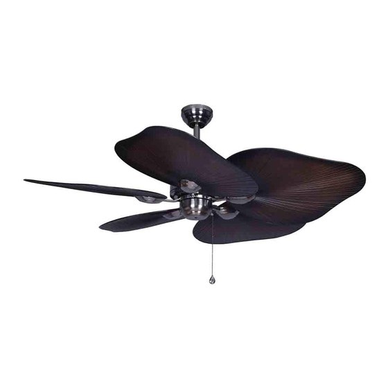
BAJA CEILING FAN
MODEL #PLM52CB5D
ITEM #0295011
Español p. 17
FOR DAMP LOCATIONS
E206035
Publicidad
Capítulos
Tabla de contenido

Manuales relacionados para Harbor Breeze PLM52CB5D


Resumen de contenidos para Harbor Breeze PLM52CB5D
- Página 1 ITEM #0295011 BAJA CEILING FAN Harbor Breeze® is a registered trademark of LF, LLC. All Rights Reserved. MODEL #PLM52CB5D Español p. 17 ATTACH YOUR RECEIPT HERE FOR DAMP LOCATIONS Serial Number Purchase Date E206035 Questions, problems, missing parts? Before returning to your retailer, call or contact our customer...
-
Página 2: Tabla De Contenido
TABLE OF CONTENTS Safety Information ………………………………………………………...……..…....2 - 3 Package Contents ……………………………………………………..……..…..…....4 Hardware Contents ........................5 Preparation ..….…………………..……………………….…………….……………....5 Initial Installation ..……………………...…………………………………………..6 - 7 Normal or Angle Style Fan Mounting ..……………………………………………………..7 - 8 Wiring ....……………………..........…………....9 - 10 Final Installation …………….……………………….…………….……....…....10 - 12 Operation Instructions ......…………………………........13 Care and Maintenance ……………………………………………………………..……………..14 Troubleshooting... -
Página 3: Safety Information
SAFETY INFORMATION DANGER If using this fan in a DAMP location, this fan must be connected to a supply circuit that is protected by a Ground Fault Circuit Interrupter (GFCI) to reduce the risk of personal injury, electrical shock or death. WARNINGS To reduce the risk of fire, electrical shock, or personal injury, mount fan to an outlet box marked "ACCEPTABLE FOR FAN SUPPORT"... -
Página 4: Package Contents
PACKAGE CONTENTS PART DESCRIPTION QUANTITY PART DESCRIPTION QUANTITY Downrod Motor Screw (preassembled) Canopy Lock Washer Mounting Bracket (preassembled) Motor Housing Canopy Mounting Screw Switch Housing (preassembled) Yoke Cover Pin (preassembled) Plastic Locking Mechanism Clip (preassembled) Blade Pull Chain Extension Canopy Cover Blade Arm Blade Arm Screw IMPORTANT REMINDER: You must... -
Página 5: Hardware Contents
HARDWARE CONTENTS (shown actual size) E3 Wire Connector Qty. 4 PREPARATION Before beginning assembly and installation of product, make sure all parts are present. Compare parts with package contents list and hardware contents above. If any part is missing or damaged, do not attempt to assemble, the product. -
Página 6: Initial Installation
INITIAL INSTALLATION Turn off circuit breakers and wall switch to the fan supply line leads. (Fig. 1) DANGER: Failure to disconnect power supply prior to installation may result in serious injury or death. Determine mounting method to use. (Fig. 2) A. -
Página 7: Normal Or Angle Style Fan Mounting
INITIAL INSTALLATION Remove motor screws (J) and lock washers (K) from underside of motor and save for bade arm (P) attachment later on. [If there are plastic motor blocks installed with the motor screws (J) and lock washers (K), discard the plastic motor blocks.] (Fig. - Página 8 FAN MOUNTING Depending on the length of downrod (A) you use, you may need to cut the lead wires back to simplify the wiring. If you decide to cut back the lead wires, it is suggested that you do so in the following manner: Ball Take the lead wires and make sure that you have...
-
Página 9: Wiring
WIRING WARNING: To reduce the risk of fire, electrical shock, or personal injury, wire connectors provided with this fan are designed to accept only one 12 gauge house wire and two lead wires from the fan. If your house wire is larger than 12 gauge or there is more than one house wire to connect to the two fan lead wires, consult an electrician for the proper size wire connectors to use. -
Página 10: Final Installation
WIRING Wrap electrical tape around each individual wire connector (AA) down to the wire as shown in Fig. 2. WARNING: Make sure no bare wire or wire strands are visible after making connections. Place green and white connections on opposite side of box from the black and blue (if applicable) connections. - Página 11 FINAL INSTALLATION Align the three blade arm screws (Q), pre-installed on the blade arm (P), with the three holes on the blade (H). Press up on the blade arm (P) firmly so that the blade arm screws (Q) come through the holes in the blade (H).
- Página 12 FINAL INSTALLATION Remove three screws from fitter plate on underside of motor housing (D). Connect male plug from motor housing (D) to female plug from switch housing (E). (Fig. 6) Make sure plugs connect tightly. Fitter Plate Male Plug Female Plug Align holes in switch housing (E) with holes in fitter plate.
-
Página 13: Operation Instructions
OPERATION INSTRUCTIONS The pull chain located on the switch housing has four positions to control fan speed. One pull is HIGH, two is MEDIUM, three is LOW and four turns the fan OFF. (Fig. 1) Switch Housing Use the fan reverse switch, located on the switch housing (B), to optimize your fan for seasonal performance. -
Página 14: Care And Maintenance
CARE AND MAINTENANCE At least twice each year, lower canopy (B) to check downrod (A) assembly, and then tighten all screws on the fan. Clean motor housing (D) with only a soft brush or lint-free cloth to avoid scratching the finish. Clean blades (H) with a lint-free cloth. You may occasionally apply a light coat of furniture polish to wood blades for added protection. -
Página 15: Warranty
WARRANTY LIMITED LIFETIME WARRANTY: Litex Industries warrants this fan to be free from defects in workmanship and materials present at time of shipment from the factory for Lifetime limited from the date of purchase. This warranty applies only to the original purchaser. Litex Industries agrees to correct any defect at no charge or, at our option, replace the ceiling fan with a comparable or superior model. -
Página 16: Replacement Parts List
REPLACEMENT PARTS LIST For replacement parts, call our customer service department at 1-800-527-1292, 8:30 a.m. - 5:00 p.m., CST, Monday - Friday. When ordering parts, please have the Model # or Item # of the fan available, which can be found on page 1. PART DESCRIPTION Downrod... - Página 17 ARTICULO #0295011 VENTILADOR DE TECHO BAJA Harbor Breeze® es marca registrada de LF, LLC. Reservados todos los derechos. MODELO #PLM52CB5D ADJUNTE SU RECIBO AQUI REGISTRADO PARA LUGARES HUMEDOS Número de serie Fecha de compra E206035 ¿Preguntas, problemas, faltan piezas? Antes de regresar a la tienda, llame o póngase en contacto con nuestro departamento de servicio al cliente al 1-800-527-1292, de 8:30 a.m.
- Página 18 INDICE DE MATERIAS Información de seguridad ....................18 - 19 Contenido del paquete ......................20 Contenido de artículos de ferretería ..................21 Preparación ....….…………………..……………………….…………….…..…. 21 Instalación inicial ......……………………………………………………………...22 - 23 Montaje del ventilador ..........……............23 - 24 Conexión de los cables .…………………………………………………...…......25 - 26 Instalación final ..………………….……...…….……....……......27 - 29 Instrucciones de funcionamiento...
-
Página 19: Información De Seguridad
INFORMACION DE SEGURIDAD PELIGRO Si va a utilizar este ventilador en un lugar HUMEDO, hay que conectar el ventilador a uncircuito de alimentación que esté protegido por un Interruptor de Circuito de Falla de Tierra (GFCI,por sus siglas en inglés) para reducir el riesgo de daño corporal, descarga eléctrica o la muerte. ADVERTENCIAS Para reducir el riesgo de incendio, choque eléctrico o daño corporal, sujete el ventilador a una caja de salida marcada "Aceptable para sostener ventilador"... -
Página 20: Contenido Del Paquete
CONTENIDO DEL PAQUETE PIEZA DESCRIPCION CANTIDAD PIEZA DESCRIPCION CANTIDAD Vástago Tornillo del motor (preensamblado) Cubierta Arandela del motor Soporte de montaje (preensamblada) Bastidor del motor Tornillo para montaje de la Caja del interruptor cubierta (preensamblado) Cubierta del yugo Clavija (preassemblada) Mecanismo de seguridad Sujetador (preensamblado) de plástico... -
Página 21: Contenido De Artículos De Ferretería
CONTENIDO DE ARTICULOS DE FERRETERIA (se muestra en tamaño natural) Conector para cable E3 Ctd. 4 PREPARACION Antes de empezar con el ensamblaje e instalación del producto, asegúrese de tener todas las piezas. Compare las piezas con la lista del contenido del paquete y el contenido de artículos de ferretería más arriba. -
Página 22: Instalación Inicial
INSTALACION INICIAL Apague todos los disyuntores del circuito y el interruptor de pared a la línea de suministro de electricidad del ventilador. (Fig. 1) PELIGRO: El no desconectar el suministro de electricidad antes de la instalación puede resultar en daños graves o la muerte. Determine el método de montaje. -
Página 23: Montaje Del Ventilador
INSTALACION INICIAL 5. Saque los tornillos del motor (J) y las arandelas de seguridad (K) del lado inferior del motor Y guárdelos para sujetar los brazos para las paletas (P) más adelante. [Si hay también soportes de plástico del motor instalados con los tornillos del motor (J) y las arandelas de seguridad (K), deseche los soportes de plástico.] (Fig. - Página 24 MONTAJE DEL VENTILADOR Dependiendo del largo del vástago (A) que use, es posible que tenga que cortar los cables principales para facilitar la conexión de cables. Si usted elige cortar los cables principales, se le sugiere hacerlo de la manera que sigue: bola Toma los cables principales y asegúrese de que los haya jalado completamente por la parte superior del...
-
Página 25: Conexión De Los Cables
CONEXION DE LOS CABLES ADVERTENCIA: Para reducir el riesgo de incendio, choque eléctrico o daño corporal, los conectores para cable provistos con este ventilador son diseñados para aceptar sólo un cable de calibre 12 de la casa y dos cables principales del ventilador. - Página 26 CONEXION DE LOS CABLES NOTA: El cable negro es positivo (conduce energía eléctrica) del ventilador. El cable azul es positivo (conduce energía eléctrica) del juego de luz. El cable blanco es tanto para el ventilador como para el juego de luz. El cable verde o pelado es el que hace tierra.
-
Página 27: Instalación Final
INSTALACION FINAL Localice los dos tornillos para montaje de la cubierta (L) en la parte inferior del soporte de montaje (C) y quite el tornillo para montaje de la cubierta (L) que está localizado más cerca del extremo abierto del soporte de montaje (C). - Página 28 INSTALACION FINAL Localize los tornillos del motor (J) y las arandelas de seguridad (K) que se quitaron en el paso 5 de la página 23. Introduzca un solo tornillo del motor (J), con la arandela de seguridad (K), en el brazo para la paleta (P) para sujetar el brazo para la paleta (P) al motor y apriete el tornillo del motor (J) parcialmente.
-
Página 29: Instrucciones De Funcionamiento
INSTALACION FINAL Alinee los agujeros en la caja del interruptor (E) con los agujeros en la placa de conexión. Vuelva a introducir los tornillos que se quitaron en el paso anterior y apriete bien todos los tornillos. (Fig. 7) placa de conexión Sujete la extensión para la cadena de encendido (O) provista en uno de los paquetes de artículos de... -
Página 30: Cuidado Y Mantenimiento
INSTRUCCIONES DE FUNCIONAMIENTO Use el interruptor de reversa, localizado en la caja del interruptor (E), para optimizar el uso del ventilador durante las estaciones del año. (Fig. 2) Un ventilador de techo le permitirá subir el termostato en verano y bajarlo en invierno sin notar una diferencia en su comodidad. -
Página 31: Localización De Fallas
LOCALIZACION DE FALLAS Si tiene alguna pregunta acerca del producto, por favor llame al servicio al cliente al 1-800-527-1292, de 8:30 a.m. a 5:00 p.m., hora central, de lunes a viernes. ADVERTENCIA: Antes de proseguir, desconecte la electricidad, quitando los fusibles o cortando el suministrode energía de los circuitos para evitar un choque eléctrico. -
Página 32: Garantía
GARANTIA GARANTIA LIMITADA DE POR VIDA: Litex Industries garantiza que este ventilador está libre de defectos de mano de obra y de materiales desde la fecha de salida de la fábrica por el tiempo de por vida limitada a partir de la fecha de compra. Esta garantía sólo se aplica al comprador original. -
Página 33: Lista De Piezas De Repustos
LISTA DE PIEZAS DE REPUESTOS Para piezas de repuesto, llame a nuestro departamento de servicio al cliente al 1-800-527-1292, de 8:30 a.m. a 5:00 p.m., hora central, de lunes a viernes. Al pedir piezas, por favor tenga listo el No. de modelo o No.