Tabla de contenido
Publicidad
Idiomas disponibles
Idiomas disponibles
Enlaces rápidos
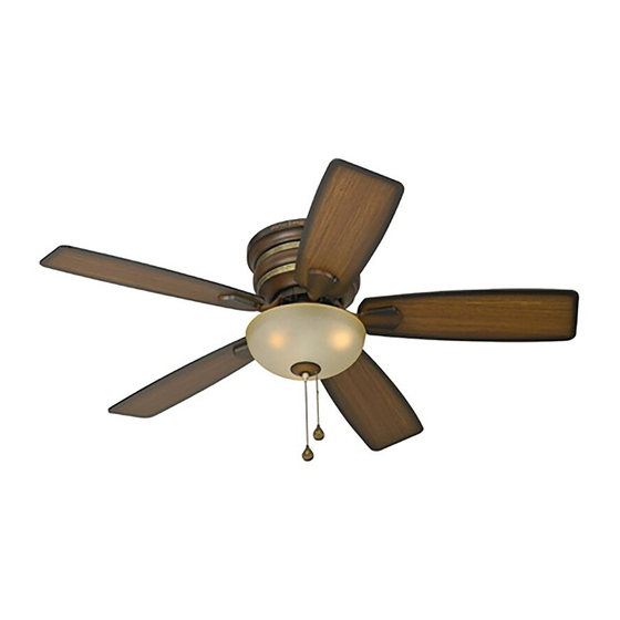
ITEM #0312115
CEDAR HILL CEILING FAN
Harbor Breeze® is a registered trademark
MODEL #PEH44BCW5MC
of LF, LLC. All Rights Reserved.
español p. 17
E206035
Questions, problems, missing parts? Before returning to your retailer, call our customer
service department at 1-800-527-1292, 8:30 a.m.-5 p.m., CST,
Monday-Friday.
1
Publicidad
Capítulos
Tabla de contenido

Manuales relacionados para Harbor Breeze PEH44BCW5MC


Resumen de contenidos para Harbor Breeze PEH44BCW5MC
- Página 1 ITEM #0312115 CEDAR HILL CEILING FAN Harbor Breeze® is a registered trademark MODEL #PEH44BCW5MC of LF, LLC. All Rights Reserved. español p. 17 E206035 Questions, problems, missing parts? Before returning to your retailer, call our customer service department at 1-800-527-1292, 8:30 a.m.-5 p.m., CST,...
-
Página 2: Tabla De Contenido
TABLE OF CONTENTS Safety Information ......………………………………………………………..….3 Package Contents ......…………………………………………………………..4 Hardware Contents ......…………………………………………………...5 Preparation ........….…………………..……………………….…..6 Initial Installation ..........……………………...………....6 - 7 Wiring ....................……......8 - 9 Final Installation ....………………….………….............9 - 12 Fan Operation ..........……………………………...…..…....13 Care and Maintenance .......………………………..………...…..…....13 Troubleshooting ...........………...……………………..…..…..14 Warranty ......…………………………………….………………....…..….15 Replacement Parts List .......………………………..………...…..….....16... -
Página 3: Safety Information
SAFETY INFORMATION READ AND SAVE THESE INSTRUCTIONS Please read and understand this entire manual before attempting to assemble, install or operate the product. If you have any questions regarding the product, please call customer service at 1-800-527-1292, 8:30 a.m.-5:00 p.m., CST, Monday-Friday. 1. -
Página 4: Package Contents
PACKAGE CONTENTS Part Description Quantity Motor Housing Mounting Plate Switch Housing Cap (pre-attached to motor assembly) Motor Assembly Light Kit Fitter Glass Shade Blade Arm Blade Candelabra Base Bulb Pull Chain Extension (in hardware pack) Finial Plate (pre-attached to light kit fitter) Finial (pre-attached to light kit fitter) IMPORTANT REMINDER: You must use... -
Página 5: Hardware Contents
HARDWARE CONTENTS Part Description Quantity Part Shown to Size Motor Screw (10 in motor; 1 in hardware pack) 3/16 Blade Screw (in hardware pack) 5.4M/M Lock Washer (10 in motor; 1 in hardware pack) Blade Washer (in hardware pack) E3 Wire Connector (in hardware pack) Motor Assembly Mounting Screw (pre-attached in mounting plate) Lock Washer (for use with Part FF) -
Página 6: Preparation
PREPARATION 1. Before beginning assembly, installation or operation of product, make sure all parts are present. Compare parts with package contents list and diagram above. If any part is missing or damaged, do not attempt to assemble, install or operate the product. Estimated Assembly Time: 120 minutes Tools Required for Assembly (not included): electrical... -
Página 7: Aa Motor Screw (10 In Motor; 1 In Hardware Pack)
INITIAL INSTALLATION Fig. 3 3. Locate motor assembly mounting screws (FF) on underside of mounting plate (B). Remove the motor assembly mounting screw (FF) with a red dot, along with the lock washer (GG)--save for later use. Partially loosen the other two motor assembly Red Dot mounting screws (FF). -
Página 8: Wiring
WIRING WARNING: To reduce the risk of fire, electrical shock, or personal injury, wire connectors provided with this fan are designed to accept only one 12 gauge house wire and two lead wires from the fan. If your house wire is larger than 12 gauge or there is more than one house wire to connect to the two fan lead wires, consult an electrician for the proper size wire connectors to use. -
Página 9: Final Installation
WIRING Fig. 2 2. Wrap electrical tape around each wire connector (EE) down to the wire as shown in Fig. 2. Warning: Make sure no bare wire or wire strands are visible after making connections. Place green and white connections on opposite side of box from the black and blue (if applicable) connections. -
Página 10: Dd Blade Washer (In Hardware Pack)
FINAL INSTALLATION Fig. 2 2. Locate three large screws at top of motor housing (A). Align large screws with slots on the edges of the mounting plate (B). Turn motor housing (A) clockwise, to the RIGHT, until it no longer turns. (Fig. 2) Note: It is extremely important that you make sure that you turn the motor housing (A) all the way to Large... -
Página 11: Hh Hex Nut (Pre-Attached To Light Kit Fitter)
FINAL INSTALLATION Fig. 5 5. If you wish to USE the light kit, remove three screws from switch housing cap (C) and remove switch housing cap (C) from switch housing. Locate Switch Housing BLUE and WHITE wires in switch housing labeled “FOR LIGHT”... - Página 12 FINAL INSTALLATION Fig. 8 8. Align holes in switch housing cap (C) with holes in switch housing. [Note: Make sure to align gap on top edge of the switch housing cap Switch Housing (C) with the reverse switch on switch housing for the correct fit.] Re-insert screws that were removed in Step 5 on the previous page and use a Phillips screwdriver to secure all screws.
-
Página 13: Fan Operation
FAN OPERATION Fig. 1 1. The pull chain located on the switch housing has four positions to control fan speed. One pull is HIGH, two is MEDIUM, three is LOW and four turns the fan OFF. (Fig. 1) Switch Housing Fig. -
Página 14: Troubleshooting
TROUBLESHOOTING WARNING: Before beginning work, shut off the power supply to avoid electrical shock. Problem Possible Cause Corrective Action Fan does not move. 1. Reverse switch not engaged. 1. Push switch firmly either up or down. 2. Power is off or fuse is blown. 2. -
Página 15: Warranty
WARRANTY LIMITED LIFETIME WARRANTY: Litex Industries warrants this fan to be free from defects in workmanship and materials present at time of shipment from the factory for Lifetime limited from the date of purchase. This warranty applies only to the original purchaser. Litex Industries agrees to correct any defect at no charge or, at our option, replace the ceiling fan with a comparable or superior model. -
Página 16: Replacement Parts List
REPLACEMENT PARTS LIST For replacement parts, call our customer service department at 1-800-527-1292, 8:30 a.m.-5:00 p.m., CST, Monday-Friday. When ordering parts, please have the Model # or Item # of the fan available, which can be found on page 1. The following parts are replaceable: Part Description... -
Página 17: Ventilador De Techo Cedar Hill
ARTICULO #0312115 VENTILADOR DE TECHO CEDAR HILL Harbor Breeze® es marca registrada de MODELO #PEH44BCW5MC LF, LLC. Reservados todos los derechos. E206035 ¿Preguntas, problemas, faltan piezas? Antes de regresar a la tienda, llame o póngase en contacto con nuestro departamento de servicio al cliente al 1-800-527-1292, de 8:30 a.m. a... - Página 18 INDICE DE MATERIAS Información de seguridad ..……………………………………………......19 Contenido del paquete ....………………………………………………………..20 Contenido de artículos de ferretería ....………………………………....21 Preparación ..........….…………………..………………....22 Instalación inicial ..........……………………………………..22 - 24 Conexión de los cables .........…………………………………….24 - 26 Instalación final ....……………….…………….…….………………….…....26 - 29 Funcionamiento del ventilador ....….................
-
Página 19: Información De Seguridad
INFORMACION DE SEGURIDAD POR FAVOR LEA Y GUARDE ESTAS INSTRUCCIONES Por favor lea el instructivo entero antes de tratar de ensamblar, instalar o hacer funcionar el producto. Si tiene alguna pregunta acerca del producto, por favor llame al servicio al cliente al 1-800-527-1292, de 8:30 a.m. -
Página 20: Contenido Del Paquete
CONTENIDO DEL PAQUETE Pieza Descripción Cantidad Bastidor del motor Placa de montaje Cubierta de la caja del interruptor (sujetada de antemano a la unidad del motor) Unidad del motor Conectador para el juego de luz Pantalla de vidrio Brazo para la paleta Paleta Bombilla de base candelabro Extensión para la cadena de encendido... -
Página 21: Contenido De Artículos De Ferretería
CONTENIDO DE ARTICULOS DE FERRETERIA Se muestra la pieza Pieza Descripción Cantidad en tamaño natural Tornillo del motor (10 en el motor; 1 en el paquete de artículos de ferretería) Tornillo para la paleta 4,76 mm (en paquete de artículos de ferretería) Arandela de seguridad 5,4 M/M (10 en el motor;... -
Página 22: Preparación
PREPARACION 1. Antes de empezar con el ensamblaje e instalación del producto, asegúrese de tener todas las piezas. Compare las piezas con la lista y los diagramas del "Contenido del paquete" en la página anterior. Si falta alguna pieza o se encuentra dañada, no trate de ensamblar, instalar o hacer funcionar el producto. - Página 23 INSTALACION INICIAL Fig. 2 2. Asegúrese de que las paletas (H) del ventilador quedarán a por lo menos 30 pulgadas (76,2 cm) de cualquier obstrucción 76,2 cm y a por lo menos 7 pies (2,13 m) arriba del min. 2,13 m nivel del piso.
-
Página 24: Conexión De Los Cables
INSTALACION INICIAL 6. Use el agujero cuadrado en la placa en la parte Fig. 6 superior de la unidad del motor (D) y colóquelo en el gancho en forma de "J" en la placa de montaje (B) para sostener el ventilador mientras se hace la conexión de cables. -
Página 25: Ventilador Y Luz Controlados Por Dos Interruptores De Pared
CONEXION DE LOS CABLES VENTILADOR CONTROLADO POR CADENA DE 1B. VENTILADOR CONTROLADO POR CADENA ENCENDIDO, LUZ POR INTERRUPTOR DE PARED DE ENCENDIDO, LUZ POR INTERRUPTOR DE Fig. 1B NEGRO 120 V cables NEGRO (INTERUPTOR DE PARED) PARED: Si usted piensa controlar la luz del ventilador de corriente DEL TECHO BLANCO... -
Página 26: Importante
CONEXION DE LOS CABLES Fig. 3 IMPORTANTE: El usar un interruptor con reductor de luz de gama completa para controlar la velocidad del ventilador causará un zumbido recio en el ventilador. Para reducir el riesgo de incendio o choque eléctrico, NO use un interruptor con reductor de luz de gama completa para controlar la velocidad del ventilador. - Página 27 INSTALACION FINAL Fig. 3 3. Parcialmente introduzca tres tornillos para la paleta (BB), junto con tres arandelas para la paleta (DD), para sujetar un brazo para la paleta (G) a una paleta (H). Luego, apriete cada tornillo para la paleta (BB), empezando con el de en medio.
- Página 28 INSTALACION FINAL Fig. 6A Fig. 6B 6. Perfore la cubierta de la caja del interruptor (C) con destornillador en el mero centro para que se caiga la tapa. (Fig. 6A) Quite la tuerca hexagonal (HH) y la arandela de seguridad (II) de la varilla roscada en la parte superior tapa arandela del conectador para el juego de luz (E).
- Página 29 INSTALACION FINAL Fig. 9 9. Instale las tres bombillas de base candelabro (I) de 40 vatios máx. incluidas. (Fig. 9) Importante: Cuando necesite reemplazar las bombillas, por favor permita que se enfríen las bombillas y la pantalla de vidrio (F) antes de tocarlas.
-
Página 30: Funcionamiento Del Ventilador
FUNCIONAMIENTO DEL VENTILADOR Fig. 1 1. La cadena de encendido localizada en la caja del interruptor tiene cuatro posiciones para controlar la velocidad del ventilador. Jálela una vez para la velocidad ALTA, dos veces para la velocidad MEDIA, caja del interruptor tres veces para la velocidad BAJA y cuatro veces para APAGAR el ventilador. -
Página 31: Cuidado Y Mantenimiento
CUIDADO Y MANTENIMIENTO Baje el bastidor del motor (A) para inspeccionar la unidad del motor (D) por lo menos dos veces al año, y luego apriete todos los tornillos. Limpie el bastidor del ventilador (A) solamente con un cepillo suave o un paño que no tenga pelusa para no rayar el acabado. Limpie las paletas (H) con un paño que no tenga pelusa. - Página 32 LOCALIZACION DE FALLAS Problema (cont.) Causa posible (cont.) Acción correctiva (cont.) El ventilador funciona 1. No se instalaron bien la(s) 1. Instale la(s) bombilla(s) de pero la luz no (si aplica). bombilla(s). nuevo. 2. No se conectaron correctamente 2. Verifique que se conectaron los cables en la caja de salida.
-
Página 33: Garantía
GARANTIA GARANTIA LIMITADA DE POR VIDA: Litex Industries garantiza que este ventilador está libre de defectos de mano de obra y de materiales desde la fecha de salida de la fábrica por el tiempo de por vida limitada a partir de la fecha de compra. Esta garantía sólo se aplica al comprador original. -
Página 34: Lista De Piezas De Repuestos
LISTA DE PIEZAS DE REPUESTOS Para piezas de repuesto, llame a nuestro departamento de servicio al cliente al 1-800-527-1292, de 8:30 a.m. a 5:00 p.m., hora central, de lunes a viernes. Al pedir piezas, por favor tenga listo el No. de modelo o No. de artículo del accesorio para iluminación, que se pueden encontrar en la página 17).