Moretti Forni T Serie Manual De Instrucciones
Ocultar thumbs
Ver también para T Serie:
- Manual instrucciones (121 páginas) ,
- Manual instrucciones (99 páginas) ,
- Manual instrucciones (257 páginas)
Capítulos
Tabla de contenido

Manuales relacionados para Moretti Forni T Serie


Resumen de contenidos para Moretti Forni T Serie
- Página 1 Manuale di istruzioni Instructions manual Manuel d’instructions Bedienungsanleitung Manual instrucciones T75G T97G Forno a gas Gas oven Four a gaz Gas Ofen Horno a gas 0705 Cod.73300440 Ver.: A10...
-
Página 7: Tabla De Contenido
INDICE 01 SPECIFICHE TECNICHE 02 INSTALLAZIONE 03 FUNZIONAMENTO 04 MANUTENZIONE ORDINARIA 05 MANUTENZIONE STRAORDINARIA 06 CATALOGO RICAMBI Nota: Il presente catalogo é predisposto per la lettura in cinque lingue. Istruzioni originali in Italiano e traduzioni delle istruziuoni originali in Inglese, Francese, Tedesco e Spagnolo. GARANZIA Norme e regolamentazione La garanzia è... -
Página 8: Specifiche Tecniche
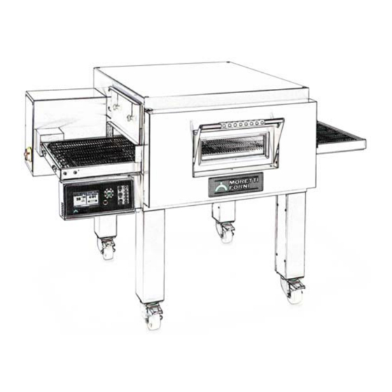
In alcuni paesi la marcatura CE potrebbe essere accettata ma si SPECIFICHE TECNICHE richiede comunque da parte degli Istituti nazionali un esame DESCRIZIONE DELL’APPARECCHIATURA dell’apparecchiatura secondo le norme nazionali. L’apparecchiatura e’ composta da una camera di cottura attraversata da un nastro trasportatore che porta il prodotto, lo stesso viene cotto DIMENSIONI D’INGOMBRO E PESI (Vedi Fig.1) dal soffiaggio di aria riscaldata tramite un bruciatore con premiscelazione aria-gas sottoposto a controllo elettronico modulante... -
Página 9: Collegamento Gas
POSIZIONAMENTO, MONTAGGIO ATTENZIONE! Dopo avere posizionato l’apparecchiatura nel INSTALLAZIONE E SPAZI MANUTENTIVI punto previsto e serrato i freni delle ruote, provvedere a munirsi ATTENZIONE! Nel posizionamento, montaggio, installazione e di almeno 4 staffe adeguatamente robuste che assicurino collegamenti sono da rispettare le seguenti prescrizioni: l’apparecchio al pavimento od al muro (ad esempio per - Leggi norme... -
Página 10: Funzionamento
2.5.2 SCARICO GAS COMBUSTI E VAPORI ATTENZIONE! Verificare che i conduttori collegati nella spina ATTENZIONE! E’ RESPONSABILITA’ elettrica non presentino punti di contatto tra loro. PROPRIETARIO MUNIRSI MANTENERE NOTA! Controllare che il senso di rotazione sia quello indicato ADEGUATO SISTEMA DI VENTILAZIONE dalla freccia posta sul retro dell’apparecchiatura (fig.20). -
Página 11: Controllo Del Funzionamento
La possibilità di funzionamento dipende dalla pressione d'entrata In caso di pressione d'entrata fuori dei valori riportati avvisare disponibile (vedi dati tecnici TAB.1): l'ente erogatore del gas e non effettuare la messa in funzione In caso di pressione d'entrata fuori dei valori riportati avvisare l'ente dell'apparecchiatura prima di non aver appurato ed eliminato la erogatore del gas e non effettuare la messa in funzione causa. -
Página 12: Operazioni Preliminari Di Controllo
- Smontare la copertura bruciatore (fig.20 part.M). - Allentare la vite di tenuta all’interno della presa di pressione in - Smontare il ventilatore dalla testa bruciatore agendo sui 4 bulloni uscita della valvola gas (fig.27 part.T) (fig.24 part.P). - Collegare il manometro, correttamente azzerato, alla presa di - Smontare il cono Venturi dalla valvola gas agendo sulle tre viti pressione. -
Página 13: Impostazione Della Lingua
tutte le operazioni di controllo devono essere eseguite da funzionamento dell’apparecchiatura, non toccarli assolutamente personale tecnico specializzato munito di regolare licenza. per non ustionarsi; sovrapponendo più camere, quelle superiori Provvedere prima della messa funzione alla pulizia possono scaldarsi, non toccare le parti esterne per non ustionarsi. dell’apparecchiatura come da punto 4.2. - Página 14 22) tasto programma P4 3.6.9 FUNZIONE DEL TASTO LOCK: Questa funzione permette di bloccare, con fini di sicurezza, alcune 3.6.4 AVVIAMENTO DELL’APPARECCHIATURA operazioni: All’accensione si va direttamente alla schermata di figura 30 dove Le funzioni che vengono disattivate sono: compaiono le impostazioni relative all’ultima cottura effettuata. In - Memorizzazione dei programmi (infatti se premo il tasto alto a destra è...
-
Página 15: Manutenzione Ordinaria
fin tanto che non lo riavviamo. Questo per permettere all’operatore di In generale in caso di anomalia verificare sempre che tutte le accorgersi comunque dell’anomalia avvenuta , anche se al momento connessioni elettriche siano efficaci e che non siano presenti cavi dell’anomalia nessuno fosse nelle vicinanze del forno. -
Página 16: Periodi Di Inattivita
Provvedere ogni giorno a fine lavorazione, dopo il raffreddamento dell’apparecchiatura, a rimuovere accuratamente da tutte le parti eventuali residui che possano essersi creati durante la cottura utilizzando un panno o spugna inumiditi, eventualmente con acqua saponata e poi sciacquare ed asciugare, pulendo le parti satinate nel verso della satinatura. -
Página 17: Manutenzione Straordinaria
ATTENZIONE ISTRUZIONI SEGUENTI RELATIVE ALLA “MANUTENZIONE STRAORDINARIA” SONO STRETTAMENTE RISERVATE PERSONALE TECNICO SPECIALIZZATO MUNITO DI REGOLARE LICENZA, RICONOSCIUTO ED ABILITATO DALLA DITTA COSTRUTTRICE. MANUTENZIONE STRAORDINARIA attenzione a non lasciare nell’ apparecchiatura quanto usato per la pulizia. OPERAZIONI PRELIMINARI DI SICUREZZA ATTENZIONE! Prima di effettuare qualsiasi operazione di 5.2.1 SMONTAGGIO COMPONENTI... - Página 18 - Infilare le due viti (fig.38 part.Y) negli appositi fori e fermare SOSTITUZIONE TERMOSTATO usando i due dadi (fig.38 part.K) posizionati sulla vite (fig.38 part.J). SICUREZZA ATTENZIONE! Verificare periodicamente la funzionalità del 5.3.2 SOSTITUZIONE COMPONENTI QUADRO termostato di sicurezza. ELETTRICO Eseguite le operazioni al punto 5.1, per la sostituzione del termostato Eseguite le operazioni al punto 5.1, per la sostituzione di componenti di sicurezza procedere come segue:...
- Página 19 5.8.1 SMONTAGGIO NASTRO gancio non devono mai andare dal verso in cui tendono ad Eseguite le operazioni al punto 5.1, per lo smontaggio del nastro agganciare, perché oltre a rovinare il nastro diventano procedere come segue: estremamente pericolose quanto potrebbe facilmente - Fare scorrere il nastro fino a che la giunzione con i tubetti arrivi agganciare eventuali lembi di abiti, arti ,anelli, bracciali ecc.
- Página 20 Eseguite le operazioni al punto 5.1, per sostituire la spina procedere Controllare la suddetta quota X in maniera precisa con un come segue: CALIBRO ed apporre il sigillo alla regolazione gas con un punto - Sfilare la copertura giunto nastro(fig.36 part.U) svitando la vite che di vernice termoresistente rossa.
-
Página 21: Catalogo Ricambi
5.19 SMANTELLAMENTO Al momento dello smantellamento dell’apparecchiatura o dei ricambi, occorre separare i vari componenti per tipologia di materiale e provvederne poi allo smaltimento in conformità a leggi e norme vigenti. CATALOGO RICAMBI Indice delle tavole: Tav.A Assieme T75G T97G Tav.B Schema elettrico T75G T97G INDICAZIONE PER L'ORDINAZIONE DELLE PARTI DI RICAMBIO... - Página 22 IT/16...
- Página 23 INDEX 01 TECHNICAL SPECIFICATIONS 02 INSTALLATION 03 OPERATION 04 ORDINARY MAINTENANCE 05 SPECIAL MAINTENANCE 06 SPARE PARTS Note: This catalogue is printed in five different languages. Original instructions in Italian and translations of the original instructions in English, French, German and Spanish. WARRANTY Standards and rules Warranty only covers the replacement free to factory of pieces eventually broken or damaged because of faulty materials or manufacture.
-
Página 24: Technical Data
TECHNICAL DATA DIMENSIONS AND WEIGHTS (see Fig.1) DESCRIPTION OF THE APPLIANCE IDENTIFICATION The oven comprises a baking chamber through which runs a When communicating with the manufacturer or service centre, conveyor belt carrying the product, which is cooked by a jet of air always give the oven SERIAL NUMBER, which can be found on the heated by a burner with an air-gas pre-mixer and electronic flame plate fixed as shown in fig.2 item M, example key (fig.3):... -
Página 25: Gas Connection
- Directives and indications issued by the gas supply network screws d. 4.8, which must be screwed into the back only in the 12 - Directives and indications issued by the electricity supply free holes diameter 4.1 mm provided (fig. 9 item F). network - The single elements that have been selected to make up the oven must be placed one on top of the other as shown in figure 9, after... - Página 26 When connection has been completed, check that the supply voltage, suction ceiling that must guarantee evacuation of combustion and cooking fumes at all times. with the appliance running, does not differ from the rated value by WARNING! The discharge of exhaust fumes must take place more than ±...
-
Página 27: Checking Operation
- Turn the appliance of as described in the instructions. - Loosen the retention screw inside the gas valve outlet pressure - Remove the pressure gauge. takeoff (fig. 27 item T) - Fasten the retention screw (fig. 23 item W) tightly. - Connect the pressure gauge to the pressure takeoff, after making - Replace the burner cover (fig.20 item M) carefully, making sure sure it has been zeroed. - Página 28 has been carried out, using a special, non-corrosive gas leak indicator % Gas acc. Percentage fan revs on start-up spray. % Gas minimo Percentage fan revs at minimum Never use a naked flame when looking for possible gas leaks. % Gas massimo Percentage fan revs at maximum - Turn the appliance off.
- Página 29 STARTING UP 3.6.3 KEYBOARD (fig. 31) WARNING! SHOULD YOU SMELL GAS: The following keys are located alongside the monitor, and details of NEVER TURN SWITCH ELECTRICAL their uses will be given later in the manual: 9) up arrow APPLIANCE THIS MIGHT TRIGGER EXPLOSION.
- Página 30 programs; or press and hold one of the above buttons for one second - Burner block to select another number. - Flame out For example: P1+P2=program N.12, or P4+P1=program N.41 When one of the above alarms occurs the control unit indicates on screen which alarm has been triggered, and turns the oven off.
-
Página 31: Periods Of Inactivity
cloth and a little soapy water, if necessary. Rinse and dry the areas, working properly anymore. Therefore they must be changed periodically as per the procedure at the point 5.14. being sure to wipe parts with satin finish in the direction of the finish. M Burner ventilator malfunction alarm Carefully clean all accessible parts. -
Página 32: Special Maintenance
WARNING FOLLOWING INSTRUCTIONS, WHICH CONCERN “SPECIAL MAINTENANCE” ARE STRICTLY RESERVED TO SPECIALIST TECHNICIANS WITH THE RELEVANT LICENSE AS WELL AS BEING APPROVED BY THE MANUFACTURER. - Remove the lock (fig.16 item H), open the clip (fig.16 item R) and SPECIAL MAINTENANCE open the front door (fig. - Página 33 - Close the panel holding the electrical components, using the - Perform the above operations in reverse order to reassemble. procedure described in point 5.3.4 - Close the panel holding the electrical components, using the NOTE! If the electronic card has to be replaced, perform a procedure described in point 5.3.4 general Reset of the appliance as described in point 5.18.
- Página 34 - Compress the belt from the right hand side (fig 41). NOTE! To unfasten it, the left hand screw must be turned - Take one of the side joint links and, after noting how the edges of clockwise; the fan will not come out of its housing unless you use the belt are fitted (fig.
- Página 35 - Replace the burner cover (fig.20 item M) carefully, making sure 5.17 CHANGING COMBUSTION CHAMBER that there are no cracks through which unfiltered air might pass. SHIELDS After carrying out the operations described in point 5.1, to change the combustion chamber shields proceed as follows: 5.15 CHANGING OR CLEANING THE BURNER HEAD NOTE! To maintain always the nominal power, the head of the...
- Página 36 UK/14...
- Página 37 TABLE DES MATIÈRES 01 SPÉCIFICATIONS TECHNIQUES 02 INSTALLATION 03 FONCTIONNEMENT 04 ENTRETIEN ORDINAIRE 05 ENTRETIEN EXTRAORDINAIRE 06 LISTE DES PIÈCES DE RECHANGE Remarque : Ce catalogue a été rédigé pour la lecture en cinq langues. Instructions originales en italien et traduction des instructions en Anglais, Français, Allemand et Espagnol.
-
Página 38: Spécifications Techniques
SPÉCIFICATIONS TECHNIQUES DIMENSIONS ET POIDS (Voir Fig. 1) DESCRIPTION DE L’APPAREIL IDENTIFICATION L’appareil est constitué par une chambre de cuisson traversée par un Pour toute communication avec le fabriquant ou avec les centres tapis transporteur qui porte le produit; la cuisson de ce dernier se fait d'assistance, mentionner toujours le NUMÉRO DE SÉRIE de par soufflage d’air chauffé... - Página 39 Tout support non fourni par le fabriquant doit être apte à garantir la - Lois et normes en vigueur relatives à l'installation des appareils à gaz dans des grandes cuisines bonne stabilité de l'appareil en toute situation. - Lois et normes en vigueur relatives aux réglages techniques des ATTENTION ! Après avoir placé...
-
Página 40: Branchement Électrique
Une fois le branchement terminé, effectuer un essai d'étanchéité du branchement à l’installation; ce branchement devra être effectué en gaz à l'aide d'un spray détecteur de fuites qui ne provoque pas de suivant l’illustration de la fig.19. corrosion. REMARQUE ! S'ASSURER QUE LES FILS DE LA PHASE Ne jamais utiliser de flammes nues pour chercher d'éventuelles NEUTRE SONT BRANCHÉS CORRECTEMENT, SINON LE fuites de gaz. -
Página 41: Contrôle Du Fonctionnement
3.1.3 CONTRÔLE DE LA PUISSANCE THERMIQUE 3.4. TRANSFORMATION ET/OU ADAPTATION POUR AVEC GAZ MÉTHANE (G20-G25-G25.1) UTILISER D'AUTRES GAZ. La puissance thermique nominale est atteinte sans gicleurs ; le ATTENTION ! Les opérations décrites ci-après doivent être réglage du gaz sur le cône Venturi (fig. 22) doit mesurer X= voir les effectuées par un personnel technique spécialisé... - Página 42 - Retirer le scellage du réglage du gaz sur le cône Venturi (fig. 22) gaz désormais utilisé sur l'appareil (voir fig. 2 en position G) sur la plaquette précédente. et, à l'aide d'un tournevis de grande dimension, tourner le réglage jusqu'à obtenir la mesure X= voir les données techniques 3.4.2 TRANSFORMATION POUR PASSER DU GPL (G30- TAB.
- Página 43 ATTENTION ! LE LOGICIEL DE L'APPAREIL EST PRÉVU - COUPER L'ALIMENTATION DU GAZ EN AGISSANT SUR PAR DÉFAUT POUR LE MÉTHANE G20. APRÈS CHAQUE LE ROBINET MANUEL EXTERNE LE PLUS PROCHE DU REMISE À ZÉRO, IL FAUDRA DONC REPROGRAMMER COMPTEUR DE GAZ. LES PARAMÈTRES INTERNES POUR LE TYPE DE GAZ - UTILISER UN TÉLÉPHONE EXTERNE POUR APPELER RÉELLEMENT UTILISÉ...
- Página 44 (dans les quatre situations différentes: en mouvement, à l’arrêt, utiliser, il suffira de rappeler le programme désiré à l'aide des touches pendant la cuisson ou pendant le préchauffage) seront toujours P1, P2, P3 ou P4; les données dudit programme apparaissent à présentes.
- Página 45 alors que, si l’appareil est en fonction, ou bien au moment où il H Alarme tapis. entrera en fonction, une icône qui représente une tirelire s'affichera à - Le motoréduteur du tapis transporteur est muni d'un système de droite de l’écran, à la place de l’icône du tapis contrôle rétroactif de la vitesse ;...
-
Página 46: Opérations Préliminaires De Sécurité
poignée avant (fig. 15, détail Q) ; mais cela doit être fait avec le choix sera proposé ; ceci afin de permettre de terminer le cycle de maximum de précaution. cuisson en cours. ATTENTION ! L’accès à l’intérieur de la chambre au moyen de ATTENTION ! Un filtre sale peut compromettre le rendement et la porte doit avoir lieu uniquement et exclusivement avec des la sécurité... -
Página 47: Entretien Extraordinaire
ATTENTION INSTRUCTIONS SUIVANTES RELATIVES L’“ENTRETIEN EXTRAORDINAIRE ” SONT STRICTEMENT RESERVEES AU PERSONNEL TECHNIQUE SPECIALISE MUNI D’UNE LICENCE SPECIFIQUE, RECONNU ET AGREE PAR LE FABRICANT. ENTRETIEN EXTRAORDINAIRE Ne pas utiliser de solvants, de produits de lessive contenant des substances agressives (chlorées, acides, corrosives, abrasives, OPÉRATIONS PRÉLIMINAIRES DE SÉCURITÉ... - Página 48 ACCÈS AUX COMPOSANTS ÉLECTRIQUES 5.3.6 REMPLACEMENT DU MOTEUR DE BANDE Après avoir remplacé les trains des balais on pourrait devoir 5.3.1 OUVERTURE DU PANNEAU PORTE-COMPOSANTS remplacer le moteur du convoyeur (Tab.A part.57). Une fois exécutées les opérations au point 5.1, procéder comme suit : ÉLECTRIQUES Après avoir effectué...
- Página 49 REMPLACEMENT DU CLAVIER DU TABLEAU DES ATTENTION ! Pour éviter tout grincement, lubrifier le tapis COMMANDES avec une huile en spray exclusivement du type homologué pour Après avoir effectué les opérations indiquées au point 5.1, pour le aliments ; elle doit être vaporisée en petite quantité, quand remplacement du clavier du tableau des commandes, suivre les l'appareil est éteint et froid, exclusivement sur les deux parties instructions reportées ci-après :...
-
Página 50: Réglage Du Contraste De L'ÉCran
5.11 PROGRAMMATION TEMPÉRATURES bonne position, comme en figure 48, sinon les remplacer selon la DEGRÉS CENTIGRADES/FAHRENHEIT procédure au point 5.14. L'unité centrale électronique peut être programmée pour représenter Avec le temps, la poussière peut avoir tendance à obstruer la tête du la température en degrés centigrades ou en degrés Fahrenheit. -
Página 51: Mise Au Rebut
- Remonter avec soin le panneau de protection du brûleur (fig. 20 détail M) en faisant attention de ne laisser aucune fissure qui pourrait laisser passer de l'air non filtré. 5.17 REMPACEMENT PANNEAUX PROTECTION DE LA CHAMBRE DE COMBUSTION Après avoir effectué les opérations indiquées au point 5.1, pour le remplacement des panneaux de protection de la chambre de combustion, suivre les instructions reportées ci-après : - Enlever le panneau arrière (fig. - Página 52 FR/16...
- Página 53 INHALT 01 TECHNISCHE ANGABEN 02 INSTALLATION 03 BETRIEB 04 ORDENTLICHE WARTUNG 05 AUSSERORDENTLICHE WARTUNG 06 ERSATZTEILKATALOG Anmerkung: Vorliegender Katalog ist in fünf Sprachen ausgeführt. Originalanweisungen auf Italienisch und Übersetzungen der Originalanweisungen auf Englisch, Französisch, Deutsch und Spanisch. GARANTIE Bedingungen und Regelungen Die Garantieleistung ist ausschließlich auf den Austausch ab Werk jener Teile beschränkt, die nachweisbar Material- oder Konstruktionsfehler aufweisen.
-
Página 54: Technische Angaben
durch nationale Institute Grundlage nationalen TECHNISCHE ANGABEN Bestimmungen gefordert wird. BESCHREIBUNG DES GERÄTS Das Gerät besteht aus einer Backkammer, die von einem Förderband RAUMBEDARF UND GEWICHTE (siehe Abb. 1) mit dem darauf befindlichen Produkt durchlaufen wird; das Produkt wird von einem Luftstrahl gebacken, der von einem Brenner mit IDENTIFIZIERUNG Luft-Gas-Gemisch elektronischer... - Página 55 AUFSTELLEN, MONTAGE, INSTALLATION UND ACHTUNG! Nachdem das Gerät an seinem Bestimmungsort RAUMBEDARF FÜR WARTUNGSARBEITEN aufgestellt und die Räder blockiert wurden, mindestens vier ACHTUNG! Beim Aufstellen, bei der Montage, der Installation ausreichend robuste Winkel besorgen, mit denen das Gerät und den Anschlüssen sind die nachstehenden Vorschriften zuverlässig an einer Wand oder am Boden verankert wird (zum einzuhalten: Beispiel für Geräte mit 1 oder 2 Kammern Abb.
-
Página 56: Betrieb
2.5.2 ABFÜHRUNG DER VERBRENNUNGSGASE UND FÜR EINIGE SEKUNDEN ZÜNDET UND SICH DANN DÄMPFE BLOCKIERT. ACHTUNG! DER BESITZER MUSS BINDEND FÜR EIN ACHTUNG! Sicherstellen, dass sich Stecker AUSREICHENDES BELÜFTUNGSSYSTEM SORGE angeschlossenen Leiter nicht untereinander berühren. TRAGEN UND DIESES AUFRECHT ERHALTEN ANMERKUNG! Kontrollieren, ob die Drehrichtung der ACHTUNG! Anschluss Abführung... - Página 57 Vor dem Anschließen an das Gasnetz sicherstellen, dass der ACHTUNG! Die internen Parameter des Geräts müssen die für den betreffenden Versorgungsgastyp geltenden sein (Punkt Versorgungsdruck des Geräts dem Wert der TAB.1 entspricht; dieser 3.4.4). Druck muss dauernd gewährleistet sein. Die Funktionsmöglichkeit hängt vom verfügbaren Einlassdruck ab Falls der Einlassdruck außerhalb der angegebenen Werte sein sollte, (siehe Technische Daten TAB .1): das Gaswerk benachrichtigen und das Gerät nicht in Betrieb setzen,...
-
Página 58: Vorbereitende Kontrollen
- Den Brennerdeckel ausbauen (Abb. 20 Detail M). Das Gerät anweisungsgemäß einschalten. - Den Ventilator vom Brennerkopf ausbauen, indem die 4 - Beim Einschalten variiert der Druck anfangs. Warten, bis der Mutterschrauben gelöst werden (Abb.24 Detail P). Brenner zündet und dann den Druck messen, der 0 mbar sein muss, - Den Venturi Konus ausbauen, indem die drei Schauben gelöst andernfalls die Kappe vom Gasventil nehmen (Abb. -
Página 59: Einstellung Der Sprache
alle Kontrollarbeiten müssen Fachpersonal Förderbands besteht die Gefahr, mitgeschleift und von der vorschriftsmäßiger Lizenz durchgeführt werden. Bewegung des Förderbands gequetscht zu werden. Vor der Inbetriebsetzung muss das Gerät wie unter Punkt 4.2 - Im Besonderen die Glasscheibe der vorderen Tür, die verstellbaren beschrieben gereinigt werden. - Página 60 17) Lock-Taste 3.6.8 ÄNDERN EINES PROGRAMMS 18) Programmiertaste P Der Zugriff auf diese Funktion ist nur möglich, wenn die Funktion 19) Programmtaste P1 Lock nicht aktiviert ist !! 20) Programmtaste P2 Soll ein zuvor gespeichertes Programm geändert werden, muss es mit 21) Programmtaste P3 Hilfe der zugeordneten Taste abgerufen werden;...
-
Página 61: Ordentliche Wartung
Nach dem Drücken der Taste OK 5 Sekunden warten, bevor das - Alarm für Überschreitung der max. Sicherheitstemperatur - Alarm für defekten Brennerventilator Neustarten des Geräts versucht wird. - Brenner blockiert Falls der Brenner kurz zündet und dann blockiert wird, muss kontrolliert werden, ob die Speisung von Phase und Nullleiter korrekt - Ausgehen der Flamme Bei Eintreten einer dieser Alarme signalisiert die Steuerzentrale am... -
Página 62: Längerer Nichtgebrauch
- Das Gerät von der Stromversorgung trennen. (Abb. 29 Detail N) auf “0” gestellt wird und die Stromzufuhr unterbrechen, indem die außerhalb des Geräts installierten - Die Gaszufuhr unterbrechen. Schalter abgeschaltet werden. - Das Gerät abdecken, um es vor Staub zu schützen. - Die Räume regelmäßig lüften. -
Página 63: Ausserordentliche Wartung
ACHTUNG DIE FOLGENDEN ANWEISUNGEN ZUR “AUSSERORDENTLICHEN WARTUNG” RICHTEN SICH AUSSCHLIESSLICH AN FACHPERESONAL MIT ORDENTGEMÄSSER LIZENZ, DAS VOM HERSTELLER ANERKANNT UND BEFUGT IST. AUSSERORDENTLICHE WARTUNG ANMERKUNG: Die gehärteten Scheiben der Türen erst reinigen, wenn sie nicht mehr heiß sind. VOBEREITENDE SICHERHEITSMASSNAHMEN Keine Lösemittel, Reinigungsmittel... - Página 64 - Schrauben Sie die Abdeckkappen der Bürsten heraus und ziehen ACHTUNG! Nicht vergessen, den Schlüssel aus dem Vorhängeschloss abzuziehen. Sie die Bürsten heraus. - Setzen Sie die neuen Bürsten ein schrauben Sie die Abdeckkappen wieder auf. ZUGRIFF AUF DIE ELEKTROKOMPONENTEN - Schließen Sie das Paneel mit den elektrischen Komponenten, wie 5.3.1 ÖFFNEN...
- Página 65 - Beim Wiedereinbau in umgekehrter Reihenfolge vorgehen und ACHTUNG! Kontrollieren, Laufrichtung darauf achten, dass die Verbinder korrekt angeschlossen werden. Förderbands mit der in Abb. 46 gezeigten übereinstimmt; die ANMERKUNG! Eine allgemeine Rücksetzung des Geräts hakenförmigen Kanten dürfen niemals in die Anhakrichtung durchführen, wie unter Punkt 5.18 beschrieben.
- Página 66 - Den eventuell beschädigten Teil der Isolierung ersetzen und mit für 5.15 AUSWECHSELN ODER REINIGEN hohe Temperaturen geeignetem Klebeband aus Aluminium isolieren. BRENNERKOPFS ANMERKUNG! Damit stets die Nennleistung gewährleistet 5.11 EINSTELLUNG DER TEMPERATUREN IN GRAD wird, muss der Brennerkopf wenigstens einmal jährlich gereinigt CELSIUS ODER GRAD FAHRENHEIT werden.
-
Página 67: Ersatzteilkatalog
- Den Brennerdeckel (Abb. 20 Detail M) sorgfältig wieder einbauen, wobei darauf zu achten ist, dass keine Spalten entstehen, durch die ungefilterte Luft eindringen könnte. 5.17 AUSWECHSELN DER SCHUTZSCHILDER DER VERBRENNUNGSKAMMER Nach Durchführung der unter Punkt 5.1 beschriebenen Operationen, die Schutzchilder des Verbrennungskammers wie folgt auswechseln: - Das hintere Paneel (Abb. - Página 68 DE/16...
- Página 69 ÍNDICE 01 CARACTERÍSTICAS TÉCNICAS 02 INSTALACIÓN 03 FUNCIONAMIENTO 04 MANTENIMIENTO ORDINARIO 05 MANTENIMIENTO EXTRAORDINARIO 06 CATÁLOGO DE LOS RECAMBIOS Nota: El presente manual se ha previsto para la lectura en cinco idiomas. Instrucciones originales en Italiano y traducciones de las instrucciones originales en Inglés, Francés, Alemán y Español.
-
Página 70: Características Técnicas
CARACTERÍSTICAS TÉCNICAS MODELO DE APARATO EN QUE SE VA A INTERVENIR. En algunos países el marcado CE podría ser aceptado pero de todas DESCRIPCIÓN DEL APARATO formas se solicita de parte de los Institutos nacionales un examen del El aparato está formado por una cámara de cocción atravesada aparato según las normas nacionales. -
Página 71: Conexiones
- Leyes y normas vigentes sobre la instalación de aparatos a ¡ATENCIÓN! Tras colocar el aparato en el punto previsto y haber gas en grandes cocinas. apretado los frenos de las ruedas, utilizar 4 bridas bien robustas - Leyes y normas vigentes sobre las instalaciones de gas. para asegurar el aparato al suelo o a la pared (por ejemplo, para el - Leyes y normas vigentes sobre las instalaciones de GPL. -
Página 72: Conexión Eléctrica
¡NOTA! ASEGURARSE DE QUE LOS HILOS DE LA FASE Y EL 2.5.2 DESCARGA DE LOS VAPORES Y DE LOS NEUTRO SE HAYAN CONECTADO CORRECTAMENTE YA GASES QUEMADOS QUE, CASO CONTRARIO, QUEMADOR ¡ATENCIÓN! PROPIETARIO ÚNICA ENCENDERÁ DURANTE ALGUNOS SEGUNDOS Y, LUEGO, SE PERSONA RESPONSABLE REALIZAR... -
Página 73: Transformación Y Adaptación Al Uso De Otros Tipos De Gas
¡ATENCIÓN! Los parámetros internos del aparato deben ser TRANSFORMACIÓN Y ADAPTACIÓN AL USO DE los previstos para el tipo de gas de alimentación (punto 3.4.4). OTROS TIPOS DE GAS La posibilidad de funcionamiento depende de la presión de ¡ATENCIÓN! Todas las operaciones descritas a continuación deben entrada disponible (consultar los datos técnicos de la TABLA 1). -
Página 74: Configuración
- Quitar el precinto del mando de regulación del gas del cono Venturi 3.4.2 TRANSFORMACIÓN DE GPL (G30-G31) A GAS METANO (G20-G25-G25.1). (fig. 22) y, con la ayuda de un destornillador de boca plana grande, girar Para la transformación de GPL a gas metano, efectuar las dicho mando hasta conseguir la cota X= consultar los datos técnicos operaciones siguientes: TABLA 1 para el tipo de gas de alimentación. -
Página 75: Operaciones Preliminares De Control
OK (fig. 31, ref. 13), se sale del menú sin guardar los nuevos PUESTA EN MARCHA datos configurados. ¡ATENCIÓN! EN CASO QUE SE HUELA A GAS: ¡ATENCIÓN! EL SOFTWARE DEL APARATO HA SIDO - NO ACCIONAR NINGÚN INTERRUPTOR O APARATO CONFIGURADO, POR DEFECTO, PARA EL GAS ELÉCTRICO YA QUE PUEDEN PROVOCAR UNA EXPLOSIÓN. -
Página 76: Configuración Y Modificación De Los Parámetros De Cocción
la mitad derecha de la pantalla, las ventanas varían en función de 3.6.6 EJECUCIÓN DE UNO DE LOS 20 PROGRAMAS la situación en que se encuentra, pero, en general, siempre se Si, al poner en marcha el horno, éste se encuentra en « manual » o en otro visualizan el tiempo de cocción (crossing time) y el icono que programa diferente al que se desea usar, pulsar la tecla correspondiente al representa la cinta (en las tres situaciones diferentes: en... -
Página 77: Estado Del Aparato
de la pantalla, en lugar del icono de la cinta, se visualiza un icono H Alarma de la cinta que representa una hucha. - El motorreductor de la cinta transportadora posee un sistema de control retroactivo de la velocidad que, en caso de que no gire, entra en alarma. I Alarma de llama apagada 3.6.15 ESTADO DEL APARATO figura 32... -
Página 78: Operaciones
El tejido del filtro (fig. 37, ref. F) se puede limpiar con agua, tratado con ¡ATENCIÓN! Al término de la jornada laboral, recordarse de desenchufar el aparato de la alimentación eléctrica y de un chorro de agua o golpeándolo y, luego, dejarlo secar. cerrar la llave del gas situada aguas arriba del horno. -
Página 79: Mantenimiento Extraordinario
ATENCIÓN SIGUIENTES INSTRUCCIONES RELATIVAS “MANTENIMIENTO EXTRAORDINARIO” ESTÁN RESERVADAS PERSONAL TÉCNICO ESPECIALIZADO EN POSESIÓN DE UNA REGULAR LICENCIA, AUTORIZADO Y HABILITADO POR EL FABRICANTE. MANTENIMIENTO EXTRAORDINARIO Está prohibido utilizar para limpiar detergentes dañinos para la salud. OPERACIONES PRELIMINARES NOTA: No limpiar los vidrios templados de las puertas cuando aún SEGURIDAD están calientes. -
Página 80: Acceso A Los Componentes Eléctricos
ACCESO A LOS COMPONENTES ELÉCTRICOS 5.3.6 SUSTITUCIÓN DEL MOTOR DE LA CINTA Tras la sustitución de algunos sets de escobillas puede ser necesario 5.3.1 APERTURA PANEL sustituir el motor de la correa (Tab.A part.57). Tras efectuar las operaciones descritas en el punto 5.1, hay que: COMPONENTES ELÉCTRICOS Tras efectuar las operaciones descritas en el punto 5.1, para abrir - Abrir el panel de los componentes eléctricos efectuando las operaciones... -
Página 81: Desarmado Y Rearmado De La Cinta
- Colocarlo en un banco de trabajo y desconectar cuidadosamente 5.8.3 INVERSIÓN DEL SENTIDO DE ROTACIÓN DE LA el teclado. CINTA TRANSPORTADORA - Limpiar esmeradamente la superficie del cuadro. - Tras efectuar las operaciones descritas en el punto 5.1, para invertir el - Comprobar que, en la parte transparente del nuevo teclado, no sentido de rotación de la cinta hay que: esté... -
Página 82: Regulación Del Contraste De La Pantalla
- Desmontar el cabezal del quemador y sustituirlo o limpiarlo; la N° limpieza se ha de efectuar con un chorro de aire comprimido dirigido contra la red del cabezal del quemador en el sentido ilustrado en la fig. 49 comprobando que todo el polvo salga por la parte opuesta. grados centígrados grados Fahrenheit - Asegurarse de que las distancias de la bujía de encendido o del detector... -
Página 83: Procedimiento
- Para el escudo posterior, desenroscar los cuatro tornillos de bloqueo y extraer el escudo por el orificio de aspiración de aire del ventilador. - Para el escudo anterior, desmontar la cinta y los sopladores de la manera descrita en el punto 5.2.1, desenroscar los cuatro tornillos de bloqueo y extraer el escudo por el orificio de aspiración de aire del ventilador. - Página 84 ES/16...
- Página 85 TAB.1 Categoria: Category: IT-CZ-ES-GR-IE-PT-GB-CH-SK-TR II2H3+ T75G Catégorie: Kategorie: Categoría: Tipo - Type - Type - Bauweise - Tipo A3 - B23 Portata termica nominale 17 kW Rated thermal capacity - Puissance thermique nominale - Nennwärmeleistung - Capacidad térmica nominal Portata termica ridotta 7 kW Reduced thermal capacity - Puissance thermique réduite - Verringerte Wärmeleistung - Capacidad térmica reducida Consumo Metano - Methane consumption - Consommation de Méthane - Erdgasverbrauch...
- Página 86 TAB.1 Categoria: Category: II2ELL3B/P T75G Catégorie: Kategorie: Categoría: Tipo - Type - Type - Bauweise - Tipo A3 - B23 Portata termica nominale 17 kW Rated thermal capacity - Puissance thermique nominale - Nennwärmeleistung - Capacidad térmica nominal Portata termica ridotta 7 kW Reduced thermal capacity - Puissance thermique réduite - Verringerte Wärmeleistung - Capacidad térmica reducida Consumo Metano - Methane consumption - Consommation de Méthane - Erdgasverbrauch...
- Página 87 TAB.1 Categoria: Category: T75G Catégorie: Kategorie: Categoría: Tipo - Type - Type - Bauweise - Tipo A3 - B23 Portata termica nominale 17 kW Rated thermal capacity - Puissance thermique nominale - Nennwärmeleistung - Capacidad térmica nominal Portata termica ridotta 7 kW Reduced thermal capacity - Puissance thermique réduite - Verringerte Wärmeleistung - Capacidad térmica reducida Consumo Metano - Methane consumption - Consommation de Méthane - Erdgasverbrauch...
- Página 88 TAB.1 Categoria: Category: AT-CH II2H3B/P T75G Catégorie: Kategorie: Categoría: Tipo - Type - Type - Bauweise - Tipo A3 - B23 Portata termica nominale 17 kW Rated thermal capacity - Puissance thermique nominale - Nennwärmeleistung - Capacidad térmica nominal Portata termica ridotta 7 kW Reduced thermal capacity - Puissance thermique réduite - Verringerte Wärmeleistung - Capacidad térmica reducida Consumo Metano - Methane consumption - Consommation de Méthane - Erdgasverbrauch...
- Página 89 TAB.1 Categoria: Category: AL-BA-BG-CZ-DK-EE-FI-HR II2H3B/P T75G Catégorie: Kategorie: Categoría: LT-LV-MK-NO-RO-SE-SI-UA Tipo - Type - Type - Bauweise - Tipo A3 - B23 Portata termica nominale 17 kW Rated thermal capacity - Puissance thermique nominale - Nennwärmeleistung - Capacidad térmica nominal Portata termica ridotta 7 kW Reduced thermal capacity - Puissance thermique réduite - Verringerte Wärmeleistung - Capacidad térmica reducida...
- Página 90 TAB.1 Categoria: Category: I2E(R)B T75G Catégorie: Kategorie: Categoría: Tipo - Type - Type - Bauweise - Tipo A3 - B23 Portata termica nominale 17 kW Rated thermal capacity - Puissance thermique nominale - Nennwärmeleistung - Capacidad térmica nominal Portata termica ridotta 7 kW Reduced thermal capacity - Puissance thermique réduite - Verringerte Wärmeleistung - Capacidad térmica reducida Consumo Metano - Methane consumption - Consommation de Méthane - Erdgasverbrauch...
- Página 91 TAB.1 Categoria: Category: I2Esi T75G Catégorie: Kategorie: Categoría: Tipo - Type - Type - Bauweise - Tipo A3 - B23 Portata termica nominale 17 kW Rated thermal capacity - Puissance thermique nominale - Nennwärmeleistung - Capacidad térmica nominal Portata termica ridotta 7 kW Reduced thermal capacity - Puissance thermique réduite - Verringerte Wärmeleistung - Capacidad térmica reducida Consumo Metano - Methane consumption - Consommation de Méthane - Erdgasverbrauch...
- Página 92 TAB.1 Categoria: Category: II2L3B/P T75G Catégorie: Kategorie: Categoría: Tipo - Type - Type - Bauweise - Tipo A3 - B23 Portata termica nominale 17 kW Rated thermal capacity - Puissance thermique nominale - Nennwärmeleistung - Capacidad térmica nominal Portata termica ridotta 7 kW Reduced thermal capacity - Puissance thermique réduite - Verringerte Wärmeleistung - Capacidad térmica reducida Consumo Metano - Methane consumption - Consommation de Méthane - Erdgasverbrauch...
- Página 93 TAB.1 Categoria: Category: CY-IS-MT I3B/P T75G Catégorie: Kategorie: Categoría: Tipo - Type - Type - Bauweise - Tipo A3 - B23 Portata termica nominale 17 kW Rated thermal capacity - Puissance thermique nominale - Nennwärmeleistung - Capacidad térmica nominal Portata termica ridotta-Thermic capacity-Portèe thermiqueNennwärmebelast. Capacidad térmica 7 kW Consumo GPL - LPG consumption - Consommation de GPL - GPL Verbrauch G30 (kg/h)
- Página 94 TAB.1 Categoria: Category: II2HS3B/P T75G Catégorie: Kategorie: Categoría: Tipo - Type - Type - Bauweise - Tipo A3 - B23 Portata termica nominale 17 kW Rated thermal capacity - Puissance thermique nominale - Nennwärmeleistung - Capacidad térmica nominal Portata termica ridotta 7 kW Reduced thermal capacity - Puissance thermique réduite - Verringerte Wärmeleistung - Capacidad térmica reducida Consumo Metano - Methane consumption - Consommation de Méthane - Erdgasverbrauch...
- Página 95 TAB.1 Categoria: Category: II2E3B/P T75G Catégorie: Kategorie: Categoría: Tipo - Type - Type - Bauweise - Tipo A3 - B23 Portata termica nominale 17 kW Rated thermal capacity - Puissance thermique nominale - Nennwärmeleistung - Capacidad térmica nominal Portata termica ridotta 7 kW Reduced thermal capacity - Puissance thermique réduite - Verringerte Wärmeleistung - Capacidad térmica reducida Consumo Metano - Methane consumption - Consommation de Méthane - Erdgasverbrauch...
- Página 96 TAB.1 T75G AU (Australia) AGA CERTIFICATION NUMBER: 7282 Nominal Gas Consumption @ Max Rate (MJ/h) Nominal Gas Consumption @ Economy / Ignition Rate (MJ/h) Gas Inlect Connection (Fig. 10 item W). CONESNAPED MALE GAS MANIFOLD G 1/2" Natural gas Universal LPG Gas % Gas acc.
- Página 97 TAB.1 TOWN GAS Group 5 6inWC=15mbar (SG Singapore) T75G Tipo - Type - Type - Bauweise - Tipo A3 - B23 Portata termica nominale 17 kW Rated thermal capacity - Puissance thermique nominale - Nennwärmeleistung - Capacidad térmica nominal Portata termica ridotta 7 kW Reduced thermal capacity - Puissance thermique réduite - Verringerte Wärmeleistung - Capacidad térmica reducida Consumo - Consumption - Consommation –...
- Página 98 TAB.2 COLLEGAMENTO ELETTRICO – ELECTRIC CONNECTION - CONNECTION ELECTRIQUE - ELEKTRISCHER ANSCHLUß - CONEXIÓN ELÉCTRICA T75G T97G Tensione nominale V230 1N Nominal Tension – Tension nominale – Nominalspannung – Tensión nominal Frequenza 50 Hz Frequency – Fréquence – Frequenz – Frecuencia Assorbimento nominale 700 W Nominal Absorption –...
- Página 99 T75G T97G CV/60 T75G T97G CV/15 T75G T97G...
- Página 100 PREDISPOSTO PER... ADJUSTED FOR ..ESSAYE AU GAZ... EINGESTELLT FÜR... PREPARADO PARA...
- Página 101 Pericolo schiacciamento Organi in movimento Caution crushing Moving parts Danger ècrasement Organes en mouvement Zwetschgefahr Bewegende organe Peligro de aplastaimento Organos en movimiento Pericolo tensione Senso di rotazione Caution voltage Sense of rotation Danger tension Sense de rotation Spannungsgefahr Rotationsrichtung Peligro tension Sentido de rotaciòn Pericolo temperatura elevata...
- Página 111 COD. XXXX...
- Página 117 Rif. Denominazione Designation Denomination Bezeichnung Denominación Treccia porta Main door braid Garniture porte Dichtung Tür Junta puerta Treccia portello Door braid Garniture hublot Dichtung kleine Tür Junta puerta con vidrio Guarnizione albero motore Drive shaft gasket Garniture arbre moteur Dichtung Motorwelle Junta eje motor Scudo posteriore bruciatore Burner rear shield...
- Página 118 230V 220V 220V 100VA 50VA 1 2 3 GIALLO VERDE-YELLOW GREEN BLU-BLUE MARRONE-BROWN MARRONE-BROWN ROSSO-RED BIANCO-WHITE BIANCO NERO-WHITE BLACK 3 4 5 ROSSO NERO-RED BLACK VERDE NERO-GREEN BLACK BIANCO GIALLO-WHITE YELLOW BIANCO VIOLA-WHITE VIOLET BIANCO ARANCIO-WHITE O RANGE 1 2 3 4 5 6 8 9 10 11 74800210 Revisione 01 T75G T97G V230 1N...
- Página 119 Rif. Denominazione Designation Denomination Bezeichnung Denominación Fusibile Fuse Fusible Sicherung Fusible Termostato di sicurezza Safety thermostat Thermostat de sécurité Sicherheitsthermostat Termostato de seguridad Interruttore generale Main switch Interrupteur général Hauptschalter Interruptor general Sensore controllo rotazione Rotation control sensor Capteur contrôle rotation Sensor Drehkontrolle Sensor de control de rotación Morsettiera entrata rete...