Moretti Forni T Serie Manual Instrucciones
Ocultar thumbs
Ver también para T Serie:
- Manual instrucciones (121 páginas) ,
- Manual de instrucciones (119 páginas) ,
- Manual instrucciones (257 páginas)
Tabla de contenido
Publicidad
Idiomas disponibles
Idiomas disponibles
Enlaces rápidos
Publicidad
Capítulos
Tabla de contenido

Manuales relacionados para Moretti Forni T Serie


Resumen de contenidos para Moretti Forni T Serie
- Página 1 Manuale di istruzioni Instructions manual Manual d’instructions Bedienungsanleitung Manual instrucciones T75E T97E TT98E Forno elettrico Electric oven Four electrique Elektrische Ofen Horno Eléctrico Cod.73341170 Ver.: A9...
-
Página 3: Dichiarazione Ce Di Conformita
- m a i l : m a r k e t i n g @ m o r e t t i f o r n i . c o m DICHIARAZIONE DI CONFORMITA’ MORETTI FORNI S.P.A. Il costruttore Indirizzo del costruttore Via A. - Página 4 We declare under sole responsability that the products to which this declaration relates is in conformity with the following standards <> following the provisions of the directives<>.
-
Página 5: Tabla De Contenido
INDICE 01 SPECIFICHE TECNICHE 02 INSTALLAZIONE 03 FUNZIONAMENTO 04 MANUTENZIONE ORDINARIA 05 MANUTENZIONE STRAORDINARIA 06 CATALOGO RICAMBI Nota: Il presente catalogo é predisposto per la lettura in cinque lingue. Istruzioni originali in Italiano e traduzioni delle istruzioni originali in Inglese, Francese, Tedesco e Spagnolo. GARANZIA Norme e regolamentazione La garanzia è... -
Página 6: Specifiche Tecniche
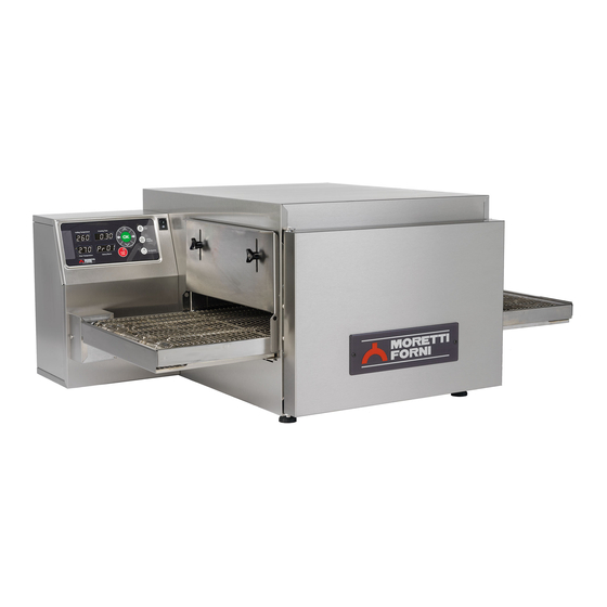
pericoli di asfissia, in particolare per i bambini. Al termine del ciclo 1 SPECIFICHE TECNICHE di vita dell’apparecchio, smaltirlo presso le isole di recupero 1.1 DESCRIZIONE DELL’APPARECCHIATURA autorizzate dalla legge. L’apparecchiatura e’ composta da una camera di cottura attraversata da un nastro trasportatore che porta il prodotto, lo stesso viene cotto SPECIFICHE AMBIENTALI dal soffiaggio di aria riscaldata tramite resistenze elettriche;... -
Página 7: Funzionamento
2.4.1 COLLEGAMENTO ELETTRICO FUNZIONAMENTO ATTENZIONE! Il collegamento elettrico deve essere effettuato esclusivamente da personale qualificato in osservanza delle OPERAZIONI PRELIMINARI DI CONTROLLO vigenti prescrizioni elettrotecniche. ATTENZIONE! Prima di iniziare le fasi d’avviamento Prima di iniziare la procedura di collegamento verificare che il dell’apparecchiatura si deve verificare che tutte le operazioni di sistema di messa a terra sia realizzato in accordo alle norme collegamento e messa a terra siano state eseguite correttamente. - Página 8 Se desidero far partire la cottura premo il tasto “Start” (a meno che IMPOSTAZIONE DELLA LINGUA: per effettuare l’impostazione della lingua è necessario premere non ci sia l’indicazione di scarto massimo consentito tra cielo e contemporaneamente i tasti “freccia a sinistra” e “freccia su”, platea, vedere a tal proposito il paragrafo 3.2.18) a cui segue sullo selezionare quindi la lingua muovendosi con i tasti freccia su e giù...
- Página 9 a questo punto sullo schermo compariranno i dati del programma regolare e, successivamente, con i tasti “freccia su” e “freccia giù” prescelto, dopodiché se desidero iniziare la cottura premo il tasto impostare la cifra voluta. start (vedi punto 3.2.3). Per ciascun orario deve essere anche impostato il valore “ON” per l'accensione o OFF per lo spegnimento affinchè...
- Página 10 La segnalazione, sia acustica che visiva resta fin tanto che non H Timer inserito. premiamo il tasto STOP. La segnalazione di allarme resta anche se effettivamente la condizione di allarme cessa di esserci , supponiamo STATO DELL’APPARECCHIATURA figura 31 ad esempio che la temperatura superi per un momento la soglia I Apparecchiatura spenta.
-
Página 11: Pulizia Ordinaria
copiati risiederanno nella directory principale (root) del Tutti gli accorgimenti sono determinati la buona dispositivo. conservazione dell’apparecchiatura e la loro mancata osservanza In entrambi i casi i file vengono così denominati: PR_xx.T98 con xx potrebbe causare seri danni che esulano dalla garanzia ed da 01 a 20. -
Página 12: Manutenzione Straordinaria
ATTENZIONE ISTRUZIONI SEGUENTI RELATIVE ALLA “MANUTENZIONE STRAORDINARIA” SONO STRETTAMENTE RISERVATE PERSONALE TECNICO SPECIALIZZATO MUNITO DI REGOLARE LICENZA, RICONOSCIUTO ED ABILITATO DALLA DITTA COSTRUTTRICE. 5 MANUTENZIONE STRAORDINARIA NOTA: Non pulire i cristalli temperati degli sportelli quando sono ancora caldi. 5.1 OPERAZIONI PRELIMINARI DI SICUREZZA Non utilizzare solventi, prodotti detergenti contenenti sostanze ATTENZIONE! Prima di effettuare qualsiasi operazione di aggressive (clorate, acide, corrosive, abrasive, ecc…) o utensili... - Página 13 - Infilare le soffianti superiori. - Eseguire le operazioni inverse per il rimontaggio. - Chiudere la porta anteriore (fig.10 part.S), se la porta non si chiude - Chiudere il pannello porta componenti elettrici seguendo la vuol dire che le soffianti non sono arrivate in posizione, non forzare procedura al punto 5.3.3.
-
Página 14: Sostituzione Delle Resistenze
- Sostituire il termostato e posizionare correttamente il sensore come - Eseguire le operazioni inverse per il rimontaggio delle nuove, verificato in precedenza attraverso la camera di cottura. ripristinare la parte di coibentazione eventualmente danneggiata - Eseguire le operazioni inverse per il rimontaggio. prestando attenzione che non arrivi ai contatti elettrici. - Página 15 - Sfilare il nastro trasportatore dalla camera di cottura eseguendo le 5.9.3 INVERSIONE SENSO DI ROTAZIONE NASTRO operazioni indicate nel punto 5.2.1, porlo su di un piano di lavoro TRASPORTATORE dotati di una pinza a becchi lunghi. -Eseguite le operazioni al punto 5.1, per l’ inversione del senso di rotazione del nastro procedere come segue: 5.9.1 SMONTAGGIO NASTRO - Sfilare il nastro trasportatore dalla camera di cottura eseguendo le...
-
Página 16: Catalogo Ricambi
- Scollegare elettricamente il ventilatore e rimuovere la staffa con il 5.15 SOSTITUZIONE DELLA SPINA DI TRASCINAMENTO ventilatore svitando le 3 viti fissaggio (fig. 38 part. K-Z) NASTRO - Rimuovere il pannello posteriore camera di cottura svitando le viti Il trascinamento dell’albero del nastro avviene tramite una spina di di fissaggio. - Página 17 INDEX 01 TECHNICAL DATA 02 INSTALLATION 03 OPERATION 04 ORDINARY MAINTENANCE 05 SPECIAL MAINTENANCE 06 LIST OF SPARE PARTS Note: This catalogue is printed in five different languages. Original instructions in Italian and translations of the original instructions in English, French, German and Spanish.
-
Página 18: Technical Specifications
1 TECHNICAL SPECIFICATIONS 2.3 ENVIRONMENTAL SPECIFICATIONS To ensure that the oven operates properly, it is advisable to comply 1.1 DESCRIPTION OF THE APPLIANCE with the following limits: The oven comprises a baking chamber through which runs a Working temperature: +5°C ÷ +40°C conveyor belt carrying the product, which is cooked by a jet of air Relative humidity: 15% ÷... -
Página 19: Electrical Connection
2.4.1 ELECTRICAL CONNECTION - Particular attention must be paid to the warning signs on the WARNING! Electrical connection must only be carried out by oven (fig.4a/b), which must be undamaged and easily legible. If specialised personnel, in compliance with current local state this is not the case, replace them. -
Página 20: Starting The Oven
3.2.1 SCREEN (fig.28) to guarantee that the cooking temperature is reached. It is The T75E-T97E is switched on by turning the switch (fig.14 part.N) possible to remove this constraint at the operator’s discretion, to position “1”; the TT98E is switched on by pressing a button but outside a range of 20°C (T75E-T97E) or 15°C (TT98E) it is (fig.14 part.R). - Página 21 displayed asking which program is to be stored? Select the program If the timer is switched on, this is shown by the words “TIMER ON” using keys P1 P2 P3 or P4 using the method described in point 3.2.5. on the screen (bottom centre). When the switch on time is reached, an intermittent buzzer will sound (for about a minute) to warn that the oven is about to switch 3.2.7 MODIFYING A PROGRAM...
- Página 22 Contactor/pressure switch failure (during the start phase, it If “OK” is pressed the oven enters free mode, the message disappears checks the integrity of the power and pressure switch contacts) and the oven can be used in a traditional manner. Electric panel overtemperature: indicates that the electrical part If “OK”...
-
Página 23: Periods Of Inactivity
3.4 USE make sure that none of the cleaning equipment has been left After setting the desired cooking parameters, prepare the product to inside. be cooked on a suitable support (pizza mesh, etc.), making sure that it does not come out through the perforated part of the mesh; use a 4.3 PERIODS OF INACTIVITY baker’s shovel to transfer it onto the conveyor belt at the baking If the appliance is not to be unused for a long period:... -
Página 24: Special Maintenance
WARNING FOLLOWING INSTRUCTIONS, WHICH CONCERN “SPECIAL MAINTENANCE” ARE STRICTLY RESERVED TO SPECIALIST TECHNICIANS WITH THE RELEVANT LICENSE AS WELL AS BEING APPROVED BY THE MANUFACTURER. 5 SPECIAL MAINTENANCE 5.2.1 REMOVING COMPONENTS WARNING! Some of the operations listed here below, such as 5.1 PRELIMINARY SAFETY OPERATIONS belt removal, need to be carried out by at least two people. - Página 25 T75E-T97E: Loosen the cable clamp (fig.11 item M). - Open the panel holding the electric components on the gear motor - Slide the electrical panel outwards (fig.17 item Z), allowing the side, as described in point 5.3.1 power cable to slide through the cable clamp (fig.11 item N). - Dismantle the gear motor, take it to a worktop, and replace the - Insert the two screws (fig.17 item Y) in the holes provided and motor.
-
Página 26: Replacing The Heating Elements
- To replace the conveyor belt follow the procedure described in - Remove the bottom casing from the belt joint (fig.36 part F) point 5.2.2. - Remove the belt motor protective casing (fig.36 part E) TT98E: the oven has four thermocouples: Top, Bottom, Left and - Remove the top or bottom hatches (fig.36 part.A-B-C-D) Right. - Página 27 outer side and then the inner one, if necessary with the aid of a long 5.10 REPLACING THE TEMPERED GLASS nosed clamp. After carrying out the operations described in 5.1 above, to replace - Repeat the above operation on the opposite side link. the tempered glass proceed as follows: - Hook up the intermediate pieces (fig.25), and with the aid of the -Open the front door (fig.15 item Q) and remove the four screws...
-
Página 28: List Of Spare Parts
- Carry out the steps in reverse order to reassemble. 5.18 DISPOSAL NOTE: make sure that the rotation direction is the same as When the oven or spare parts are dismantled, the various components shown on the panel (fig. 38 part U). must be separated according to type of material, and then disposed of in conformity with current laws and regulations. - Página 29 TABLE DES MATIÈRES 01 SPÉCIFICATIONS TECHNIQUES 02 INSTALLATION 03 FONCTIONNEMENT 04 ENTRETIEN ORDINAIRE 05 ENTRETIEN EXTRAORDINAIRE 06 LISTE DES PIÈCES DE RECHANGE Remarque: Ce catalogue a été rédigé pour la lecture en cinq langues. Instructions originales en italien et traduction des instructions en Anglais, Français, Allemand et Espagnol.
-
Página 30: Spécifications Techniques
L'emballage doit être recyclé conformément aux normes en vigueur ; 1 SPÉCIFICATIONS TECHNIQUES s'assurer que les matériaux en plastique sont entreposés dans des 1.1 DESCRIPTION DE L’APPAREIL lieux surs pour éviter tout risque d'asphyxie, en particulier pour les L’appareil est constitué par une chambre de cuisson traversée par un enfants. -
Página 31: Branchement Électrique
présente lorsque l’appareil est en fonction et elle doit savoir où 2.4.3 BRANCHEMENT ÉLECTRIQUE AU RÉSEAU LAN (EN sont entreposées les clés (à proximité de l’appareil), afin de OPTION) pouvoir ouvrir la porte en cas de situations d’urgence Le branchement au réseau LAN s'effectue au moyen de la connexion décrite à... -
Página 32: Programmation De La Langue
Lors de l’allumage du pupitre de commande, après quelques températures, et cela au gré de l’opérateur, mais - au-delà de la secondes, lorsque le Logo de Moretti Forni est affiché, une page- plage de 20°C (T75E-T97E) ou de 15°C (TT98E) - l’obtention des écran comme celle représentée dans la fig. - Página 33 - Temps maximum de cuisson Standard 20 minutes. le mot de passe programmé est le chiffre 1 1 1 1 ) et tant qu'il n'a pas Le motoréducteur du ruban transporteur est équipé d’un dispositif été modifié, il n'est pas nécessaire de confirmer ce mot de passe). électronique de contrôle des tours qui, indépendamment du poids présent sur le ruban, garantit l’uniformité...
-
Página 34: Activation De La Fonction Economy
- Le motoréducteur du ruban transporteur est équipé d’un système de électrique soit rétabli, avant que se soit écoulée l’heure de mise en fonction. protections électriques qui, en cas d’absorption excessive, arrêtent le motoréducteur. - Le moteur de la ventilation est équipé d’une protection thermique 3.2.14 FONCTION ECONOMY La fonction “Economy”... -
Página 35: Entretien Ordinaire
Quand on appuie sur la touche “OK” pour dégager les températures d'urgence passée, tourner le bouton vers la gauche pour le de la valeur de réglage de la limitation, un message du type indiqué débloquer (fig. 14 détail O). dans la fig. 33 est visualisé, pour signaler qu’il faut faire attention. Après avoir appuyé... -
Página 36: Périodes D'INactivité
ATTENTION! Chaque jour éliminer soigneusement éventuelles graisses qui auraient débordé en phase de cuisson car elles pourraient causer de possibles combustions et déflagrations. ATTENTION! Ne pas laver l’appareil en utilisant des jets d’eau directs ou sous pression. Eviter que l’eau ou les éventuels produits utilisés entrent en contact avec les parties électriques. -
Página 37: Entretien Extraordinaire
ATTENTION INSTRUCTIONS SUIVANTES RELATIVES L’“ENTRETIEN EXTRAORDINAIRE ” SONT STRICTEMENT RESERVEES AU PERSONNEL TECHNIQUE SPECIALISE MUNI D’UNE LICENCE SPECIFIQUE, RECONNU ET AGREE PAR LE FABRICANT. 5 ENTRETIEN EXTRAORDINAIRE ATTENTION! Ne pas laver l’appareil en utilisant des jets d’eau directs ou sous pression. Eviter que l’eau ou les éventuels 5.1 OPÉRATIONS PRÉLIMINAIRES DE SÉCURITÉ... - Página 38 détail Z), soulever le ruban transporteur du côté du moteur de composants positionné du côté du motoréducteur, tourner le panneau quelques centimètres et enfiler le joint central du ruban. latéral et visser les 2 vis de fixation (fig.16 détail L). - Contrôler que la transmission soit alignée, enfiler la couverture du joint du ruban (fig.
-
Página 39: Remplacement Des Résistances
- Fermer le panneau porte-composants électriques, en effectuant la - Fermer le panneau porte-composants en suivant la procédure procédure indiquée au point 5.3.3. indiquée au point 5.3.3. - Pour remonter la bande transporteuse, suivre la procédure indiquée TT98E: le four est muni de deux thermostats de sécurité au point 5.2.2. - Página 40 24), accrocher avant la partie latérale externe, puis celle interne, 5.7 REMPLACEMENT DE L’ÉCRAN LCD DU PUPITRE DE COMMANDE éventuellement à l’aide de la pince à becs longs. Après avoir effectué les opérations indiquées au point 5.1, pour le - Répéter cette opération pour la maille du côté opposé. remplacement de l’écran LCD du pupitre de commande, suivre les - Accrocher les pièces intermédiaires (fig.
-
Página 41: Réglage Du Contraste De L'ÉCran
ATTENTION! Vérifier que le sens de rotation du ruban détail H) de manière à éviter une déformation excessive de la corresponde à celui qui est indiqué dans la fig. 27; les extrémités plaque de support du moteur. latérales en forme de crochet ne doivent jamais aller depuis le - Effectuer les opérations inverses pour le remontage. -
Página 42: Liste Des Pièces De Rechange
5.16 REMPLACEMENT DES PRESSOSTATS (uniquement TT98E) Le four est muni de deux pressostats indépendants pour le côté droit (fig.36 détail P) et pour le côté gauche du four (fig.36 détail Q). En l'absence de ventilation du côté correspondant, il désactivera les résistances (en cas de détection d'une anomalie au niveau de la température du CIEL, concentrer les recherches dans la partie gauche du four ;... - Página 43 INHALTSVERZEICHNIS 01 TECHNISCHE ANGABEN 02 INSTALLATION 03 BETRIEB 04 ORDENTLICHE WARTUNG AUSSERORDENTLICHE WARTUNG AUSTAUSCHTEILKATALOG Anmerkung: Vorliegender Katalog ist in fünf Sprachen ausgeführt. Originalanweisungen auf Italienisch und Übersetzungen der Originalanweisungen auf Englisch, Französisch, Deutsch und Spanisch. GARANTIE Bedingungen und Regelungen Die Garantieleistung ist ausschließlich auf den Austausch jener Teile ab Werk beschränkt, die festgestellte Material- oder Konstruktionsfehler aufweisen.
-
Página 44: Technische Angaben
Die Verpackung muss vorschriftsmäßig entsorgt werden; im 1 TECHNISCHE ANGABEN Besonderen muss Plastikmaterial sicher verwahrt werden, damit es 1.1 BESCHREIBUNG DES GERÄTES nicht in die Hände von Kindern gelangt, für die es eine Das Gerät besteht aus einem Backelement, das von einem Erstickungsgefahr darstellt. -
Página 45: Betrieb
Von den zum Gebrauch des Gerätes autorisierten und geschulten 2.4.3 ELEKTROVERBINDUNG LAN-NETZ Personen, muss zumindest eine bei Gerätebetrieb stets anwesend sein (OPTION) und den Aufbewahrungsort der Schlüssel (in der Nähe des Gerätes) Die Verbindung mit dem LAN-Netz erfolgt mit Hilfe des kennen, um die Tür in eventuell auftretenden Gefahrensituationen Anschlusses der Abb. -
Página 46: Einschalten Des Gerätes
Uhrzeiten für jeden Wochentag ermöglicht; die Funktion “Economy” 25) Programmtaste P4 oder Sparfunktion, die in Backpausen aktiviert wird; die Funktion “Lock”, die bestimmte Operationen von einem Passwort abhängig 3.2.3 EINSCHALTEN DES GERÄTES machen, damit der Gebrauch des Gerätes auch nicht geschultem Nach dem Einschalten und der einige Sekunden dauernden Anzeige Personal ermöglicht wird. - Página 47 können mit den Pfeiltasten neue Werte für das Datum und die 3.2.5 AUSFÜHRUNG EINES DER 20 PROGRAMME Befindet man sich beim Einschalten des Geräts im manuellen Modus Uhrzeit eingegeben werden (Pfeil nach links und rechts: bewegen oder in einem anderen als dem gewünschten Programm, genügt es zwischen den einzelnen Feldern, Pfeil auf und ab: zum Ändern);...
- Página 48 3.2.16 ANZEIGE VON ALARMEN ACHTUNG! Ist das Gerät bei erneutem Start noch immer Am Bildschirm der Zentrale werden bei Funktionsstörungen diese defekt, das Gerät mit Prozedur entsprechend Punkt 3.3 stoppen Arten von ALARMEN angezeigt. N); das Speisekabel aus der Steckdose ziehen und den 1) Alarm Stillstand Förderband Kundendienst kontaktieren.
-
Página 49: Ordentliche Wartung
Drückt man “OK”, um die beiden Temperaturen voneinander zu sind cirka 25-35 Minuten erforderlich, , nachdem sich die lösen und die voreingestellte Abweichung von 20° wird nicht Temperatur stabilisiert hat, kann mit dem Backen begonnen werden. überschritten, erlischt die Meldung und erscheint erst wieder, wenn ACHTUNG! Das Einlegen und die Entnahme des zu backenden die Temperaturabweichung überschritten wird. - Página 50 verwendeten Gegenstände in den Kammern liegen geblieben sind. 4.3 STILLSTAND FÜR LÄNGERE ZEITRÄUME Wird das Gerät für längere Zeit nicht benutzt: - Das Gerät von der Stromversorgung trennen. - Das Gerät abdecken, um es vor Staub zu schützen. - Den Raum periodisch lüften. - Das Gerät reinigen, bevor es erneut benutzt wird.
-
Página 51: Ausserordentliche Wartung
ACHTUNG DIE FOLGENDEN ANWEISUNGEN ZUR “AUSSERORDENTLICHEN WARTUNG” RICHTEN SICH AUSSCHLIESSLICH AN FACHPERESONAL MIT ORDENTGEMÄSSER LIZENZ, DAS VOM HERSTELLER ANERKANNT UND BEFUGT IST. 5 AUSSERORDENTLICHE WARTUNG Reinigungsmittel nicht mit den Elektroteilen in Berührung kommen. 5.1 VOBEREITENDE SICHERHEITSMASSNAHMEN Reinigung Geräts gesundheitsschädlichen ACHTUNG! Reinigungsmitteln ist verboten. - Página 52 eine Rechtwinkeligkeit erreicht wird, um die Einfügung der zentralen schließen (Abb.17 Detail Z) und die Schrauben (Abb.17 Detail V) Verbindungsstelle (Abb. 16 Detail Z) zu ermöglichen; das montieren. Für das auf der Seite des Getriebemotors liegende Förderband von der linken Motorseite her einige Zentimeter anheben Komponentenfeld, seitliche Platte...
- Página 53 - Den Thermostat mit dem entsprechenden Sensor austauschen und ANMERKUNG: Sicherstellen, dass Endstück jeden den eventuell beschädigten Teil der Isolierung ersetzen. Thermoelements stets auf dem geneigten Schnitt des Rohrs - Bei der Remontage in umgekehrter Reihenfolge vorgehen. positioniert wird, wie auf Abb. 37 Detail W dargestellt. - Die Elektrokomponentenplatte gemäß...
- Página 54 T75E T97E Eines der seitlichen Verbindungsglieder nehmen und ANMERKUNG: Sicherstellen, dass im Ofen TT98E das Endstück der ersetzten Widerstände in ihren Sitz passen, die nachdem beobachtet wurde, wie die Bandenden montiert sind (Abb. entsprechende Position in der Backkammer vergleichen, indem 24a) zuerst die Außenseite und dann die Innenseite einhaken;...
- Página 55 ACHTUNG! Kontrollieren, dass Laufrichtung Unterlegscheiben so komprimieren, (Abb. 39 Detail H) dass eine Förderbandes mit der in Abb. 27 gezeigten übereinstimmt; die Verformung der Motorhalterung vermieden wird. seitlichen hakenförmigen Enden dürfen niemals - Für den Wiedereinbau in umgekehrter Reihenfolge fortfahren. Anhakrichtung gerichtet sein, da einerseits das Förderband ANMERKUNG: Prüfen dass die Drehrichtung der Flügelräder beschädigt wird und dies andererseits sehr gefährlich ist, da sich...
-
Página 56: Austauschteilkatalog
5.16 AUSTAUSCH DER DRUCKREGLER (Nur TT98E) Der Ofen ist mit zwei unabhängigen Temperaturreglern mit manuellem Reset ausgestattet, einer für die linke Seite (Abb.14 Detail.P) und einer für die rechte Seite (Abb.36 Detail Q). Sollte auf der zugehörigen Seite die Lüftung ausfallen, wird er die Widerstände abschalten (wenn eine Störung in der OBERHITZE festgestellt wird, wird empfohlen, die Suche auf die linke Seite des Ofens zu konzentrieren, wenn eine Störung in der UNTERHITZE... - Página 57 ÍNDICE 1 CARACTERÍSTICAS TÉCNICAS 02 INSTALACIÓN 03 FUNCIONAMIENTO 04 MANTENIMIENTO ORDINARIO 05 MANTENIMIENTO EXTRAORDINARIO 06 CATÁLOGO DE LOS RECAMBIOS NOTA: El presente manual se ha previsto para la lectura en cinco idiomas. Instrucciones originales en Italiano y traducciones de las instrucciones originales en Inglés, Francés, Alemán y Español.
-
Página 58: Características Técnicas
un lugar seguro para evitar peligros de asfixia, en particular para los 1 CARACTERÍSTICAS TÉCNICAS niños. Al término de la vida del aparato, se debe eliminar en los 1.1 DESCRIPCIÓN DEL APARATO puntos de recogida y reciclaje autorizados por la ley. El aparato está... -
Página 59: Conexión Eléctrica
Antes de la puesta en marcha, limpiar el aparato de la manera 2.4.1 CONEXIÓN ELÉCTRICA ¡ATENCIÓN! La conexión eléctrica tiene que ser efectuada sólo descrita en el punto 4.2. y exclusivamente por personal cualificado en conformidad con ¡ATENCIÓN! Siempre que se ponga en marcha el aparato, hay las normas electrotécnicas. -
Página 60: Configuración Y Modificación De Los Parámetros De Cocción
La centralita se puede programar para indicar la temperatura en solera, para ello consultar el párrafo 3.2.18): en la pantalla se grados Centígrados o grados Fahrenheit; para cambiar la visualiza una solicitud de OK, y, sucesivamente, la cinta y la programación, consultar el punto 5.13. - Página 61 introducir la segunda cifra; con este criterio se pueden con un horario asociado a cada día, en la parte superior, la indicación seleccionar 20 programas diferentes (1,2,3,4,11,1213,…,44); del periodo de encendido mañana / tarde ON y apagado mañana / en la pantalla aparecen los datos del programa seleccionado, y, tarde OFF.
-
Página 62: Señalización
efectivamente ha cesado la condición de alarma. Por ejemplo, si la G Menú de puesta en marcha o configuración del timer. temperatura supera por un momento el umbral máximo previsto, H Timer activado pero, después, vuelve a los valores correctos, la alarma cesa, pero, en la pantalla de la centralita, sigue visualizándose la alarma y el aparato ESTADO DEL APARATO figura 31 permanece apagado hasta que se vuelve a poner en marcha. -
Página 63: Detención
USB. Los archivos deben situarse en el directorio principal (raíz) Todas las operaciones se han de efectuar cuando el aparato esté del dispositivo USB. frío. EXPORTACIÓN (tecla 2): los programas presentes en la Todas las operaciones de mantenimiento tienen que ser centralita se copian dentro del dispositivo USB. -
Página 64: Mantenimiento Extraordinario
ATENCIÓN SIGUIENTES INSTRUCCIONES RELATIVAS “MANTENIMIENTO EXTRAORDINARIO” ESTÁN RESERVADAS PERSONAL TÉCNICO ESPECIALIZADO EN POSESIÓN DE UNA REGULAR LICENCIA, AUTORIZADO Y HABILITADO POR EL FABRICANTE. 5 MANTENIMIENTO EXTRAORDINARIO ¡ATENCIÓN! No lavar el aparato con chorros de agua directos o bajo presión. Evitar que el agua o eventuales productos 5.1 OPERACIONES PRELIMINARES DE SEGURIDAD utilizados entren en contacto con las partes eléctricas. -
Página 65: Acceso A Los Componentes Eléctricos
- Controlar que la transmisión esté alineada, introducir la cobertura pelar, aplastar o romper los hilos o el capilar del termostato de de la junta de la cinta (fig. 16, ref. U) y enroscar el tornillo de seguridad. bloqueo (fig. 16 ref. X). - Introducir el recogedor de harina derecho y el izquierdo (fig. -
Página 66: Sustitución De Los Termopares
Abrir la puerta anterior (fig.10 part.S) y extraer la cinta - Para las resistencias superiores, quitar los laterales regulables de la transportadora de la cámara de cocción llevando a cabo las derecha y de la izquierda (fig. 10, ref. I) tras desenroscar los pomos operaciones indicadas en el punto 5.2.1. -
Página 67: Sustitución Del Teclado Del Cuadro De Mandos
Para la configuración de los idiomas remitirse al punto 3.2, para la - Montar la cinta transportadora en su sede dentro de la cámara de configuración de las escalas de temperaturas remitirse al punto 5.13. cocción y los demás componentes efectuando las operaciones descritas en el punto 5.2.2. -
Página 68: Sustitución Ventilador Posterior
- Separar el aislamiento y desmontar el panel posterior de la cámara la variación efectiva se obtiene apenas se pulsa alguna tecla o cuando de cocción tras desenroscar los tornillos de sujeción. se visualiza una nueva pantalla. - Colocarlo en un banco de trabajo, enderezar la chapa de bloqueo y Tras efectuar las operaciones descritas en el punto 5.1, para efectuar quitar el tornillo izquierdo del centro del ventilador de cocción. -
Página 69: Catálogo De Los Recambios
5.18 DESGUACE Si se desea desguazar el aparato o algunos de sus recambios, separar todos los componentes por tipología de material, y, sucesivamente, eliminarlos en conformidad con las leyes y normativas vigentes. La presencia de este símbolo significa que, en la Unión Europa, los componentes eléctricos se deben eliminar, al final de su vida, en centros de recogida diferenciada. - Página 70 ES/14...
- Página 71 TAB.1 T75/E T97/E TT98/E Potenza Max (kW) Maximum power (kW) Puissance Max. (kW) 16,55 22,55 21,8 Höchstleistung (kW) Potencia máx (kW) Assorbimento nominale (kWh) Rated absorption (kWh) Absorption nominale (kWh) 11,3 10,9 Soll-Stromaufnahme (kWh) Absorción nominal (kWh) Tensione nominale (AC) Rated voltage (AC) Tension nominale (C.A.) V400 3N (V230 3)
- Página 72 Pericolo schiacciamento Organi in movimento Caution crushing Moving parts Danger ècrasement Organes en mouvement Zwetschgefahr Bewegende organe Peligro de aplastaimento Organos en movimiento Pericolo tensione Senso di marcia Caution voltage direction of travel Danger tension Sens de marche Spannungsgefahr Laufrichtung Peligro tension Sentido de marcha Pericolo temperatura elevata...
- Página 73 Pericolo schiacciamento Organi in movimento Caution crushing Moving parts Danger ècrasement Organes en mouvement Zwetschgefahr Bewegende organe Peligro de aplastaimento Organos en movimiento Pericolo tensione Senso di marcia Caution voltage direction of travel Danger tension Sens de marche Spannungsgefahr Laufrichtung Peligro tension Sentido de marcha Pericolo temperatura elevata...
- Página 80 Fig.31 Fig.32 Fig.33...
- Página 82 Fig. 36...
- Página 83 Fig. 37...
- Página 84 Fig. 38 Fig. 38...
- Página 85 Fig. 39...
- Página 87 Rif. Denominazione Designation Denomination Bezeichnung Denominación Treccia battuta porta Door stop braid Joint tressé butée porte Dichtung Anschlag Tür Trenza tope puerta Treccia battuta portello vetro Glass door stop braid Joint tressé butée porte en verre Dichtung Anschlag Türscheibe Trenza tope puerta vidrio Guarnizione albero motore Drive shaft gasket Joint arbre moteur...
- Página 89 Rif. Denominazione Designation Denomination Bezeichnung Denominación Treccia battuta porta Door stop braid Joint tressé butée porte Dichtung Anschlag Tür Trenza tope puerta Treccia battuta portello vetro Glass door stop braid Joint tressé butée porte en verre Dichtung Anschlag Türscheibe Trenza tope puerta vidrio Albero Shaft Arbre...
- Página 90 400V 220V 1 2 3 230V 230V AT A3 230V C1 CR C2 DR D2 DS 5 6 7 RETE LAN T97E SCR T97E 230V 3 GIALLO VERDE YELLOW GREEN 74800070 Revisione 01 MOD. T75E - T97E SCR V400 3N V230 3 50Hz...
- Página 91 Rif. Denominazione Designation Denomination Bezeichnung Denominación RC1-6 Resistenze gruppo superiore Ceiling heating element Résistance groupe supérieur Widerstände obere Gruppe Resistencia superior RP1-6 Resistenze gruppo inferiore Floor heating element Résistance groupe inférieur Widerstände untere Gruppe Resistencia inferior Morsettiera Terminal board Boîte à bornes Klemmenbrett Regleta de conexiones Soppressore...
- Página 92 230V 220V 1 2 3 AT A3 C1 CR C2 DR D2 DS 5 6 7 RETE LAN GIALLO VERDE YELLOW GREEN 74800360 Revisione 00 MOD. T75/E SCR V230 1 50Hz...
- Página 93 Rif. Denominazione Designation Denomination Bezeichnung Denominación RC1-3 Resistenze gruppo superiore Ceiling heating element Résistance groupe supérieur Widerstände obere Gruppe Resistencia superior RP1-6 Resistenze gruppo inferiore Floor heating element Résistance groupe inférieur Widerstände untere Gruppe Resistencia inferior Soppressore Suppressor Suppresseur Entstörer Supresor Soppressore Suppressor...
- Página 94 230V 220V 1 2 3 RETE LAN AT A3 C1 CR C2 DR D2 DS 5 6 7 74800350 Revisione 00 MOD. T75/E SCR V230 3 60Hz...
- Página 95 Rif. Denominazione Designation Denomination Bezeichnung Denominación RC1-6 Resistenze gruppo superiore Ceiling heating element Résistance groupe supérieur Widerstände obere Gruppe Resistencia superior RP1-6 Resistenze gruppo inferiore Floor heating element Résistance groupe inférieur Widerstände untere Gruppe Resistencia inferior Soppressore Suppressor Suppresseur Entstörer Supresor Soppressore Suppressor...
- Página 96 400V 220V 1 2 3 230V RETE LAN T97E SCR 230V T97E 230V 3 230V AT A3 C1 CR C2 DR D2 DS 230V 5 6 7 74800330 Revisione 00 MOD. T97/E SCR V400 3N V230 3 60Hz...
- Página 97 Rif. Denominazione Designation Denomination Bezeichnung Denominación RC1-6 Resistenze gruppo superiore Ceiling heating element Résistance groupe supérieur Widerstände obere Gruppe Resistencia superior RP1-6 Resistenze gruppo inferiore Floor heating element Résistance groupe inférieur Widerstände untere Gruppe Resistencia inferior Soppressore Suppressor Suppresseur Entstörer Supresor Soppressore Suppressor...
- Página 98 400V 17- 39 230V 230V 141 142 144 145 147 148 230V 141 142 144 145 147 148 87 88 71 74 80 81 82 87 88 71 74 80 (39) 1 2 3 ES E2 FS F2 24Vac ES E2 FS F2 VERDE MARRONE...
- Página 99 Rif. Denominazione Designation Denomination Bezeichnung Denominación CA1-2 Condensatore motore ventole Condenser fan motor Moteur de ventilateur de condenseur Kondensator Ventilator motor Motor de ventilador del condensador Condensatore ventola raffreddamento Condenser cooling fan Ventilateur de condenseur Kondensator-Lüfter Ventilador de refrigeración del condensador C1-7 Soppressore Suppressor...